
Subscribe to Our Youtube Channel
Related Manuals for Entrust Datacard PB8500


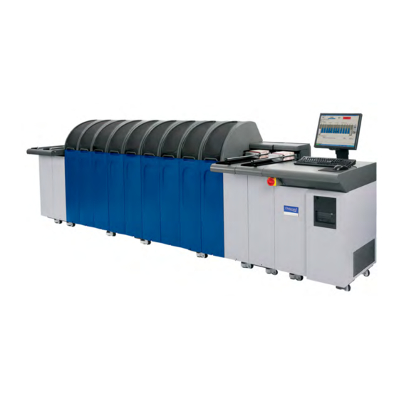
Summary of Contents for Entrust Datacard PB8500
- Page 1 Operator’s Guide Datacard Passport Issuance System PB8500 October 2021 528302-001, Rev. A...
- Page 2 Notice Please do not attempt to operate or repair this equipment without adequate training. Any use, operation or repair you perform that is not in accordance with the information contained in this documentation is at your own risk. Trademark Acknowledgments Entrust, Sigma and the hexagon design are trademarks, registered trademarks and/or service marks of the Entrust Corporation in the United States and other countries.
- Page 3 Revision Log Revision Date Description of Changes October 2021 First release of this document.
-
Page 4: Table Of Contents
Contents Chapter 1: Introduction........... . . 1 System Overview . - Page 5 Event Log ............. . 26 Process Jobs .
- Page 6 Multi-Book Chip Module ........... . . 59 Laser 450G Module .
-
Page 7: Chapter 1: Introduction
PB8500 Passport Issuance system. System Overview The PB8500 passport issuance system has a series of modules that work together to complete the personalization of elements on a passport. Available modules are defined in the following table. A system may contain duplicate modules or none of certain modules. - Page 8 Vision registration allows precise alignment between engraved elements and preprinted elements on the page. The PB8500 system can support multiple Laser module for higher throughput. Pretreatment of the booklet surface is used to increase the...
- Page 9 Module Description Single Passport This module is used to synchronize multiple Laser Engraving Buffer modules in one system to increase throughput when using teamed (ganged) engraving. Single Passport Buffer modules must be installed in pairs except when the module is directly before a Booklet Closing module. Drop On Demand The Color Inkjet Printing module uses pigment to print 1200 (DoD)
-
Page 10: Expansion Kits
Expansion Kits The following kits are included in your shipment automatically if your configuration requires additional cooling fans or power inlets. Additional Cooling Fans Larger systems may require an additional cooling fan in the Output module. The cooling fan is available as an installation kit. This kit is shipped with a system or additional modules if one is required. -
Page 11: Specifications And Requirements
System specifications and site requirements are as follows. Electrical and Environmental Specifications Electrical, Operating, and Storage Refer to the PB8500 Passport Issuance System data sheet on the Datacard website (www.entrust.com). Power Consumption The power consumption of the system is the sum of the power consumption of the Controller and all of the modules in the system. -
Page 12: Physical Requirements
Module Width/Height/Depth Controller 24 x 37.1 x 31.7 inches (61 x 94.2 x 80.5 cm) Standard PB8500 Module 10 x 50.3 x 26.9 inches (25.4 x 127.8 x 68.3 cm) Input and Output Modules 10 x 42 x 33.7 inches (The final Output module has an (25.4 x 106.7 x 85.6 cm) -
Page 13: Weight
To determine the system weight, calculate the sum of the weights for each module, the Controller, and any additional casters (11 lbs/5.0 kg). For the weight of the controller and each module, refer to the PB8500 Passport Issuance System data sheet on the Datacard website (www.entrust.com). -
Page 14: Module Interlocks
Module Interlocks Module interlocks are a safety feature that prevent operator injury. Lifting a hood causes the motors to be disabled and the interlock indicator light for the module(s) to go off. Interlock lights for the adjoining modules go off, but the adjoining modules finish processing passports and then sit idle with motors enabled. -
Page 15: Module Status Lights
Module Status Lights Each module (except for the Input and Output modules) has a status light located on the front panel to alert the operator when the module needs attention. When the light is either flashing or solid on, refer to the error message on the Controller screen for more information. -
Page 16: Supplies
Supplies Find the current supplies information on the Entrust website (www.entrust.com): Datacard Home > Product & Solutions > Supplies Related Documents The following documents provide additional information for the PB8500 system. Description Part No. Available on CD PB8500 Passport Issuance... -
Page 17: Chapter 2: System Power On And Power Off
This chapter provides procedures for starting, stopping and ® ™ pausing the Datacard PB8500 Passport Issuance system. Power On the System The system has a button for starting the Controller computer and an E-Stop switch for powering on the system modules. - Page 18 Procedure Plug the system into AC power. Turn on the Controller PC by pressing the power button on the front of the computer. Allow the Controller PC to boot up completely. Do not use the keyboard or mouse during Windows start-up. Log on to Windows.
-
Page 19: Power On Troubleshooting
Power On Troubleshooting If the system fails to start properly, use the following guidelines to isolate the most likely cause. Some of these troubleshooting scenarios may require a trained technician to isolate and correct the problem. Controller Problems If the Controller computer cannot be turned on: Verify that the main power cord is connected to the system and the facility ... -
Page 20: Power Off The System
Modules that are supplied by additional power cord inlets If you are performing service on the PB8500 system: Unplug the power cord(s) from the AC power source. Capture the female end of the AC cord into a certified lock-out device, such as the sample shown here, and lock it with a padlock. -
Page 21: Pause And Resume The System
Pause and Resume the System You can pause the system with the Controller software, or by pressing the Pause/Resume button on the Output module. The Pause/Resume button has a built-in light that shows the following system states: Green flashing light—System is paused. - Page 22 System Power On and Power Off...
-
Page 23: Chapter 3: Load Supplies
This chapter provides procedures for loading supplies in ® ™ the Datacard PB8500 Passport Issuance system. Booklets Use the following instructions to load booklets into the Passport Input Module. If the booklets are different stock, adjust for booklet thickness as described in “Adjust for Change of Booklet Thickness”... -
Page 24: Adjust For Change Of Booklet Thickness
Adjust for Change of Booklet Thickness When you load thicker or thinner booklet stock, you may need to adjust the Input Module so that the booklet separator picks only one booklet at a time. Adjustment Procedure Place two booklets into the stacker and move them forward until they both line up with the edge of the booklet separator. -
Page 25: Printheads For Inkjet Modules
Printheads for Inkjet Modules Printheads must be replaced by trained service personnel. This procedure is documented in the Drop On Demand Module Service Manual (Part No. 528211-001). Operator’s Guide... -
Page 26: Overlay Material
Overlay Material When the supply roll is empty, replace it with a new roll, as described below. Replacement Procedure Load the thin film overlay so that the registration mark is at the top of the roll. Load Supplies... - Page 27 Use the following figure as a guide to thread the thin film overlay through the standard Secure Overlay Module. Operator’s Guide...
- Page 28 Load Supplies...
-
Page 29: Chapter 4: Production
Consult your system administrator, if needed. • You can access the information in this chapter also in the PB8500 Controller software. Click the Help menu and select Help. • If you upgrade your Controller software in the future, the online help will be current with the version to which you upgrade. -
Page 30: Supply Status
Blue indicates normal operating status. Yellow indicates a cautionary condition (low supplies, input passport tray approaching empty, and so forth). Red indicates an error condition or an opened interlock. If an interlock is opened, the module, controller, and both neighboring modules on the topology turn red. -
Page 31: Job Status
Job Status You can monitor the status of individual passports within a job from the Job Details tab. The Job Details tab has information about each passport in the selected job. For more information, refer to “View Job Information” page Other Status Reporting Use the following for additional status information. -
Page 32: Event Log
Event Log The system administrator can use the Event Log tools to query and view system events for administration and troubleshooting. The Event Log is described in detail in the Controller software online help and the Administrator’s Guide. Process Jobs The following sections describe how to use the Production application to process passports. - Page 33 To select the job file, click Browse, navigate to the file location, and click Open. The file path displays in the File Name text box. Operator’s Guide...
-
Page 34: Run Jobs
Perform one of the following steps. Select the Job Setup file (click Browse, navigate to the file location, and click Open). If selection criteria are set up, select the Use Selection Criteria check box to let the program search through existing Job Setups (which contain the selection criteria) to find a name that matches the job file. -
Page 35: User Input Needed Dialog
User Input Needed Dialog If you have the Vision Verification or Quality Assurance module, the User Input Needed dialog box displays if a quality issue is detected by one of these modules. The message prompts you to take some action to make sure that the job completes successfully. -
Page 36: Preview Products
Preview Products Print preview from the Job Details tab allows you to proof a passport before it is produced. The preview shows printable graphics information such as image, text, and bar code elements. You can view non-printable information such as chip data in the Job Details screen. - Page 37 Use one of the following to open the print preview window. Right-click on the selected records and then select Print Preview. Click the Print Preview button. If more than one record is selected in the table to preview, the row is highlighted in light blue to correspond with the record being previewed in the Print Preview window.
- Page 38 The following table describes the print preview properties on the Front, Back, and Both Sides tabs. Front/Back/Both Sides Tabs Properties The “Virtual View the passport as designed in Passport Setup. Only Passport” image, text, and bar code elements display. Zoom Select the zoom level to view greater or less detail.
-
Page 39: Remake A Job
Remake a Job Use the following procedure to remake passports that were rejected. In the Production window (Applications > Production) under the All Jobs tab, select the job from the list. Select the Job Details tab. The Job Details screen contains a list of all passports in a selected job. -
Page 40: Split Jobs
Split Jobs Use the following procedure to create multiple jobs from a single job. For example, if a job contains 1000 passports, you can split it into smaller jobs. You can split a job into two jobs at a specific passport or form, or you can split a job into multiple jobs of equal size. -
Page 41: Advanced Split
Click OK. The new job is created and added to the job lists. The new job has the same name as the current job with “[001]” appended. To split a job into multiple jobs: Click Split into jobs of passport quantity. Enter the number of jobs that you want. - Page 42 Production...
-
Page 43: Search For Jobs
Search for Jobs Perform the following steps to search for jobs within the database: In the Production window (Applications > Production), select the All Jobs tab. In the left pane, select the check box next to the parameters on the jobs list that you want to use in your search. -
Page 44: Hold/Reject Passports From A Job
Hold/Reject Passports from a Job Perform one of the following procedures to hold, reject, or remove a product from a job. In the Production window (Applications > Production) under the All Jobs tab, select a job from the list. Select the Job Details tab. The Job Details screen contains a list of all passports in the selected job. -
Page 45: Production Station Reference
Production Station Reference The Production interface includes bars and tabs that display information job screens. Production Station Status Bar The status bar is viewable regardless of the tab displayed. To customize elements of the Production interface, refer to “Production Preferences” page 47. -
Page 46: Open Applications Bar
Indicator Description Hood status The Hood status indicates whether opening the hood is allowed (OK to Open Hood or Do Not Open Hood). The hood status is red when it is NOT OK to open the hood. Audit On or Off Audit ON is green when audit data is being collected. -
Page 47: All Jobs Tab
The information that displays in the Ready Jobs tab depends on the fields defined in Data Setup and the columns selected. Following is an example. Refer “Choose Columns to Be Displayed” page Column Description Name The name of the job Split Number The split number if the job has been split (the resulting jobs are numbered sequentially) -
Page 48: Filtering Tool
Column Description Status The job status Input File The Input file used for this job Filtering Tool The All Jobs tab includes a filtering tool for quickly locating jobs based on their parameters. Use the filtering tool to define specific criteria to speed up the search. -
Page 49: Job Details Tab
Search Filter Description Parameter Last Worked On Enter a number in the text box and select Hours or Days from the list. Example: If you enter 8 in the text box and select Hours from the list, the program displays only jobs worked on during the past eight hours. -
Page 50: Print Preview
Print Preview Select one or more records in the Job Details tab and select the Print Preview option to preview the selected records (print preview is also available from the right-click menu). Refer to “Preview Products” page 30 for more information. -
Page 51: Sort By Table Heading
Sort by Table Heading To enable records to be sorted by column head, click Allow Table Sorting in the Job Details tab. This setting is saved in the user preference file. Do not sort tables during a production run with a large number of passports, as this causes delays in production times. - Page 52 Click Choose Columns. Add or remove column types from the Selected Columns box by using the arrow buttons. To select multiple column types, use Shift+Click or Alt+Click. Production...
-
Page 53: Group Jobs
Click Set to Default to return to the default setting. Click OK when finished, or Cancel to exit without making changes. Group Jobs The Ready Jobs and All Jobs tabs can group jobs by group name or input file (jobs that have been loaded from the same input file) into a single display item. Select an option from the Group by list. -
Page 54: General Tab
Each tab in the tool has options for customizing Production interface elements (font, font size, FIR data, and tool tip views). Each tab has the following buttons: OK - Applies changes, Saves, and closes the dialog. Cancel - Closes the dialog, no changes are applied. Apply - Applies changes, Saves, and the dialog box continues to display. - Page 55 Use the General tab to set the font and font size for interface elements including: the text of the Production tabs (1 in the following figure), Production Statistics (2), Display Fields (3), and Extended help titles and text (4). You also can enable and customize Table Tool Tips (5) that display when the pointer hovers over a cell in a table.
-
Page 56: Toolbars Tab
Toolbars Tab Use the toolbar tab to select the font and font size for the toolbar buttons on the Production interface tabs and View Accounts dialog. You can use common settings for all toolbars or set the toolbars individually. Production... -
Page 57: Tables Tab
Tables Tab Use the Tables tab to set the font and font size for the tables on the Production interface tabs and View Accounts dialog. The font and font size changes apply to the table column headings and table values. You can use common settings for all tables or set the tables individually. Operator’s Guide... -
Page 58: Fir Record Tab
FIR Record Tab Use the FIR Record tab to enable FIR data to display at the bottom of the Production interface tabs with customized sizing and the tool tip option. You can set the font and font size for the FIR data view as well as the tool tip. You can set common preferences for all tabs, or set the tabs individually. -
Page 59: Chapter 5: Preventive Maintenance
Tasks intended for service personnel are documented in the individual PB8500 module service manuals. Cleaners, Tools, and Supplies The cleaners, tools, and supplies required to meet the PB8500 system preventive maintenance requirements are listed the Preventive Maintenance Tools and Supplies List on the CD library menu. -
Page 60: System Preventive Maintenance Tasks
System Preventive Maintenance Tasks Site personnel need to perform the following preventive maintenance tasks. Warning: Before performing maintenance, power off the Controller and remove the AC power cords. Refer to “Power Off the System” page Procedure Frequency Comments Vacuum all Once per Check for debris in both upper and lower ... - Page 61 Procedure Frequency Comments Clean the exterior As needed Clean the monitor with a soft cloth components of dampened with water. Immediately wipe the Controller the monitor dry with a clean cloth. Refer to the monitor’s manual for more specific instructions. Vacuum the keyboard.
- Page 62 Preventive Maintenance...
-
Page 63: Chapter 6: Troubleshooting
Shut down the Windows operating system. Wait 2 to 5 minutes and then power up only the Windows operating system. If the PB8500 software does not automatically open, click on the PB8500 icon. Go to the Production tab. When the machine has reached at least 11% of startup, use the red E-Stop power switch to power up the modules. -
Page 64: Remove Jammed Booklets
Remove Jammed Booklets The PB8500 system is designed to recover automatically from booklet jams. However, if automatic recovery is unsuccessful, use the following procedures to remove the booklets. You can remove a jammed booklet directly from a module without affecting other modules. -
Page 65: Page Turning Module
Page Turning Module If the booklet is still closed when it gets jammed in the Paging module, use the following procedure to remove it. Lift the module hood. Push the back plate down and remove the booklet from the rear. Caution: Be careful not to wrinkle or rip the booklet when removing. -
Page 66: Laser 450G Module
Laser 450G Module Use the following procedure to extract a jammed booklet from the Laser module. Lift the module hood. Lift the laser chamber cover. Rotate the upper booklet guide assembly (1) for clearance to remove the booklet. Remove the booklet (2) from the frame and remove the booklet from the module Troubleshooting... -
Page 67: Secure Overlay
Secure Overlay Use the following procedure to extract a jammed booklet from the Secure Overlay module. Lift the module hood. If necessary, manually push the platen carriage away from the booklet jam. Warning: Always allow the platen assembly to cool or wear protective gloves before handling the platen shoe or internal components. -
Page 68: Buffer/Closer/Qa Module
Buffer/Closer/QA Module Use the following procedure to extract a jammed booklet from the Closer or Verification module. Lift the module hood. Use your hand to dislodge the jammed booklet. Move the booklet near the closing area of the booklet track. Refer to (1) in the figure below. Lift the hinged track guide to release the horizontal opened cover of the booklet (2). - Page 69 Pull the horizontal cover of the booklet down and toward the front of the module (3). Slide the vertical cover out of the upper retaining clip. Caution: Always remove booklets from the bottom, or binding edge. Pulling the booklet from the top can damage the booklet retaining clip.
- Page 70 Troubleshooting...
Need help?
Do you have a question about the PB8500 and is the answer not in the manual?
Questions and answers