Table of Contents
Advertisement
Quick Links
CHAPTER 1
Chapter 1
INTRODUCTION
The 815 PRO (MS-6326) ATX S2 mainboard is a high-performance
computer mainboard based on Intel
to support the Intel
ness/personal desktop markets.
The Intel
ler that supports a 32-bit 133MHz SDRAM array for enhanced integrated 3D
graphics performance. It is a highly-flexible chipset which is designed to
extend the basic graphics/multimedia PC platform up to the mainstream
performance desktop platform.
The Intel
data bus interfaces within a single device. It takes advantage of the
pipelined addressing capability of the processor to improve the overall
system performance. In addition, the chipset also integrates a system
memory controller that supports a 64-bit 100/133 MHz SDRAM array.
The Intel
multifunctional I/O Controller Hub that provides the interface to the PCI Bus
and integrates many of the functions needed in today's PC platforms. It
communicates with the host controller over a dedicated hub interface and
provides added flexibility in designing cost-effective system solutions.
®
®
®
Pentium
III (FC-PGA) processor for high-end busi-
®
815 chipset integrates a Display Cache SDRAM control-
®
815 chipset implements the host address, control, and
®
82801AA (ICH) chipset is a highly integrated
815 chipset. The 815 PRO is optimized
1-1
INTRODUCTION
Advertisement
Table of Contents

Related Manuals for MSI 815 PRO


Summary of Contents for MSI 815 PRO
- Page 1 CHAPTER 1 INTRODUCTION Chapter 1 INTRODUCTION The 815 PRO (MS-6326) ATX S2 mainboard is a high-performance ® computer mainboard based on Intel 815 chipset. The 815 PRO is optimized ® ® to support the Intel Pentium III (FC-PGA) processor for high-end busi- ness/personal desktop markets.
-
Page 2: Mainboard Features
CHAPTER 1 INTRODUCTION 1.1 Mainboard Features l Support Socket370 for Intel ® ® Celeron /Pentium III(FC-PGA) processor. l Support 500MHz, 550MHz, 600MHz, 633MHz, 667MHz and up to 1GHz. Chipset l Intel ® 815 chipset. (544 BGA) - AGP 4x/2x universal slot - Support 66/100/133MHz FSB l Intel ®... - Page 3 CHAPTER 1 INTRODUCTION On-Board Peripherals l On-Board Peripherals include: - 1 floppy port supports 2 FDD with 360K, 720K, 1.2M, 1.44M and 2.88Mbytes. - 1 serial port (COMA) - 1 parallel port supports SPP/EPP/ECP mode - 4 USB ports (Rear * 2 / Front * 2) - 1 VGA port Video l GMCH chip integrated...
-
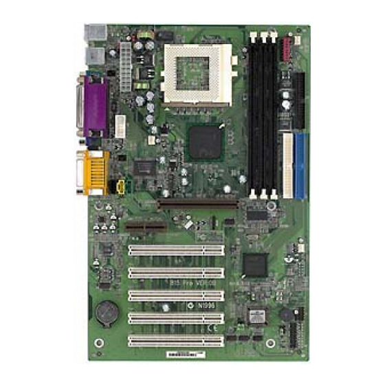
Page 4: Mainboard Layout
Line-Out Line-In J7 J6 AGP Slot AMR1 JWOL1 JMDM1 SYSFAN PCI SLOT 1 Intel FW82801AA JUSB1 PCI SLOT 2 J1 J2 JBAT1 PCI SLOT 3 JGS1 PCI SLOT 4 JGL1 BATT PCI SLOT 5 815 PRO (MS-6326) ATX S2 Mainboard... -
Page 5: Hardware Installation
Chapter 2 HARDWARE INSTALLATION 2.1 Central Processing Unit: CPU ® ® The mainboard operates with Intel Celeron /Pentium III (FC-PGA) processor. The mainboard uses a CPU socket called Socket 370 for easy CPU installation. The CPU should always have a Heat Sink and a cooling fan attached to prevent overheating. -
Page 6: Cpu Core Speed Derivation Procedure
2.1-2 CPU Core Speed Derivation Procedure The mainboard CPU Bus Frequency can be set through BIOS setup. CPU Clock = 100MHz Core/Bus ratio then CPU core speed = Host Clock x Core/Bus ratio = 700MHz... - Page 7 2.1-3 Overclocking Jumper: SW1 Overclocking is operating a CPU/Processor beyond its specified frequency. SW1 jumper is used for overclocking. Function Auto detect/Default Set from 133MHz to 160MHz through BIOS (DRAM: PC133) Set from 133MHz to 167MHz through BIOS (DRAM: PC100) Set from 100MHz to 150MHz through BIOS Set from 66MHz to 100MHz through BIOS Note: If you used this jumper for overclocking, you also need to...
-
Page 8: Fan Power Connectors: Cpufan, Sysfan
2.1-4 Fan Power Connectors: CPUFAN, SYSFAN & PSFAN These connectors support system cooling fan with + 12V. It supports three pin head connector. When connecting the wire to the connector, always take note that the red wire is the positive and should be con- nected to the +12V, the black wire is Ground and should be connected to GND. - Page 9 A battery must be used to retain the mainboard configuration in CMOS RAM. Short 1-2 pins of JBAT1 to store the CMOS data. JBAT1 Clear Data Keep Data Note: You can clear CMOS by shorting 2-3 pin, while the system is off. Then, return to 1-2 pin position.
-
Page 10: Memory Bank Configuration
2.3-1 Memory Bank Configuration The mainboard supports a maximum memory size of 512MB: It provides three 168-pin unbuffered DIMMs (Double In-Line Memory Module) sockets. It supports 32MB to 512MB DIMM memory module. -
Page 11: Memory Installation Procedures
2.3-2 Memory Installation Procedures A. How to install a DIMM Module Single Sided DIMM Double Sided DIMM 1. The DIMM slot has 2 Notch Keys “VOLT and DRAM”, so the DIMM memory module can only fit in one direction. 2. Insert the DIMM memory module vertically into the DIMM slot. Then push it in. -
Page 12: Memory Population Rules
2.3-3 Memory Population Rules 1. Supports only SDRAM DIMM. 2. To operate properly, at least one 168-pin DIMM module must be in- stalled. 3. This mainboard supports Table Free memory, so memory can be installed on DIMM1, DIMM2 or DIMM3 in any order. 4. - Page 13 Table 2.3-1 SDRAM Memory Addressing Front Side Back Side # of DIMM Population Population # of Dram Devices/ Bank Column Capacity Sides Tech. DIMM Count Config Config Count Empty Empty 32MB 16Mb 2Mb x8 32MB 64Mb 48MB 64/16Mb 2Mb x8 64MB 64Mb 4Mb x16...
- Page 14 2.4 Case Connector: J10 The Keylock, Power Switch, Reset Switch, Power LED, Speaker, and HDD LED are all connected to the JFP1 connector block. Reset Switch Power Switch Single Dual Speaker Color Color Power LED Buzzer (short pin) Keylock (Reserved) 2-10...
- Page 15 2.4-1 Power Switch Connect to a 2-pin push button switch. This switch has the same feature with JRMS1. 2.4-2 Reset Switch Reset switch is used to reboot the system rather than turning the power ON/ OFF. Avoid rebooting while the HDD LED is lit. You can connect the Reset switch from the system case to this pin.
-
Page 16: Floppy Disk Connector: Fdd
2.5 Floppy Disk Connector: FDD The mainboard also provides a standard floppy disk connector FDD that supports 360K, 720K, 1.2M, 1.44M and 2.88M floppy disk types. This connector supports the provided floppy drive ribbon cables. 2-12... -
Page 17: Hard Disk Connectors: Ide1 & Ide2
2.6 Hard Disk Connectors: IDE1 & IDE2 The mainboard has a 32-bit Enhanced PCI IDE and Ultra DMA 33/66 Con- troller that provides PIO mode 0~4, Bus Master, and Ultra DMA/33/66 function. It has two HDD connectors IDE1 (primary) and IDE2 (secondary). You can connect up to four hard disk drives, CD-ROM, 120MB Floppy (reserved for future BIOS) and other devices to IDE1 and IDE2. - Page 18 2.7-1 ATX 20-pin Power Connector: JWR This connector supports the power button on-board. Using the ATX power supply, functions such as Modem Ring Wake-Up and Soft Power Off are supported by this mainboard. This power connector supports instant power on function which means that system will boot up instantly when the power connector is inserted on the board.
- Page 19 2.8 IrDA Infrared Module Connector: J5 The mainboard provides one infrared (J5) connector for IR modules. This connector is for optional wireless transmitting and receiving infrared module. You must configure the setting through the BIOS setup to use the IR function.
- Page 20 The mainboard has a 9-pin male DIN connector for serial port COM A. This port is a 16550A high speed communication port that send/receive 16 bytes FIFOs. You can attach a mouse or a modem cable directly into this connec- tor.
- Page 21 The mainboard provides a 25 pin female centronic connector for LPT. A parallel port is a standard printer port that also supports Enhanced Parallel Port(EPP) and Extended capabilities Parallel Port(ECP). See connector and pin definition below: Parallel Port (25-pin Female) LPT 1 PIN DEFINITION SIGNAL...
-
Page 22: Keyboard Connector: Jkbms1
® The mainboard provides a standard PS/2 mouse mini DIN connector for ® ® attaching a PS/2 mouse. You can plug a PS/2 mouse directly into this connector. The connector location and pin definition are shown below: Pin5 Mouse Clock Pin6 Pin3 Pin4... -
Page 23: Joystick/Midi Connectors
2.13 Joystick/Midi Connectors You can connect joystick or game pad to this connector. Joystick/MIDI 2.14 Audio Port Connectors Line Out is a connector for Speakers or Headphones. Line In is used for external CD player, Tape player, or other audio devices. Mic is a connector for the microphones. -
Page 24: Usb Connectors
2.15 USB Connectors The mainboard provides a UHCI(Universal Host Controller Interface) Universal Serial Bus root for attaching USB devices like: keyboard, mouse and other USB devices. You can plug the USB device directly to this connector. USB Port 1 1 2 3 4 USB Port 2 SIGNAL -Data... -
Page 25: Vga Db 15 Pin Connector
2.16 VGA DB 15 Pin Connector The mainboard provides a DB 15-pin connector to connect to a VGA monitor. Analog Video Display Connector(DB15-S) Signal Description Green Blue Not used Ground Ground Ground Ground Not used Ground Not used Horizontal Sync Vertical Sync 2-21... - Page 26 Attach a power saving switch to JGS1. When the switch is pressed, the system immediately goes into suspend mode. Press any key and the system wakes up. JGS1 2-22...
- Page 27 JGL1 can be connected with an LED. There are two types of LED that you can use: 3-pin LED or 2-pin LED(ACPI request). When the 2-pin LED is connected to JGL1, the light will turn green, when system is On. During sleep mode, the 2-pin LED will change color from Green to Orange.
- Page 28 The JWOL1 connector is for use with LAN add-on cards that supports Wake Up on LAN function. To use this function, you need to set the “Wake-Up on LAN” to enable at the BIOS Power Management Setup. JWOL1 SIGNAL 5VSB MP_WAKEUP Note: LAN wake-up signal is active “high”.
- Page 29 The JMDM1 connector is for use with Modem add-on card that supports the Modem Wake Up function. To use this function, you need to set the “Power On by Ring” to enable at the BIOS Power Management Setup. JMDM1 SIGNAL MDM_WAKEUP 5VSB Note: Modem wake-up signal is active “low”.
- Page 30 2.21 Modem-In: MDM_IN The connector is for Modem with internal voice connector. Phone_In Mono_Out MDM_IN Mono_Out is connected to the Modem Speaker Out connector. Phone_In is connected to the Modem Microphone In connector. 2-26...
- Page 31 This connector is used for DVD Add on Card with Line In connector. AUX_IN 2-27...
- Page 32 This connector is for CD-ROM audio connector. CD_IN 2-28...
- Page 33 This is used to check the AGP card or any chipset temperature. The J6 is a 2-pin connector which can be inserted with a 20cm length thermistor. It is located near the chipset heatsink that monitors the chipset temperature. The BIOS setup for “TOP TECH III”...
- Page 34 The mainboard supports 2 USB Rear Port and 2 USB Front Header (shared). Function Enables the 2 Rear port and Disables the USB Front header Supports 1 Rear port and 1 USB Front header Enables the 2 USB Front header and Disables the USB Rear port 2-30...
- Page 35 The JKBV1 jumper is for setting keyboard power. This function is provided by keyboard and PS/2 mouse Wake-up function. JKBV1 5V (default) 5V Standby Disable keyboard Enable keyboard power on function power on function Note: To be able to use this function, you need a power supply that provide enough power for this feature.
- Page 36 This connector is connected to 2-pin connector chassis switch. If the Chassis is open, the switch will be short. The system will record this status. To clear the warning, you must enter the BIOS settting and clear the status. 2-32...
- Page 37 This jumper provides Vcc or 5V standby setting for USB Device Power. JUSBV2 5V (default) 5V Standby Note: If your OS supports S3 function and you are using USB device, the JUSBV2 must be set to 1-2 and the USB device must be inserted on USB Port 1.
- Page 38 This jumper is used to locked/unlocked BIOS Flash. This Jumper should be unlock when flashing/programming the BIOS. BIOS Flash BIOS Flash Locked Unlocked 2-34...
- Page 39 This jumper will enable the case speaker/buzzer to be transferred to the Audio speaker. Output to Output to Audio Chip Onboard Buzzer (default) 2-35...
- Page 40 This jumper is used to enabled/disabled Onboard Software audio, for enabling AMC97 on AMR slot. Note: This jumper will only exist if there’s no Hardware audio onboard. Function Enabled Onboard Audio Enabled AMC97 on AMR(Audio Modem Riser) Card Note: Short pin 2-3 on JP4, to be able to use AMR card. 2-36...
- Page 41 The JVTT1 is a reserved function for future Coppermine CPU. JVTT1 Function JVTT1 For Celeron For Coppermine 2-37...
- Page 42 The mainboard provides a front Universal Serial Bus connector. This is an optional USB connector for Front Panel. JUSB1 Description Description USB2- USB2+ USB3+ USB3- 2-38...
- Page 43 The mainboard provides a Special Diagnostic LED for users to be aware of their mainboard conditions. The LED helps user determine the problem of the mainboard. Diagnostic LED 2-39...
- Page 44 Diagnostic LED Function Diagnostic LED Possible Problem/ Description Solution System D-LED will hang here System Power ON. The Processor might be damage or This will start BIOS Initialization not installed properly Damage/Discharge Lithium Battery Early Chipset Initialization System D-LED will hang here Memory Detection Test The Memory module might be Testing Onboard memory size...
- Page 45 The Audio/Modem Riser specification is an open industry-standard specification that defines a hardware scalable Original Equipment Manufacturer (OEM) mainboard riser board and interface, which supports both audio and modem. AMR1 2-41...
-
Page 46: Award Bios Setup
® Chapter 3 AWARD BIOS SETUP ® Award BIOS ROM has a built-in Setup program that allows users to modify the basic system configuration. This type of information is stored in battery-backed RAM (CMOS RAM), so that it retains the Setup information when the power is turned off. -
Page 47: Status Page Setup Menu/Option Page Setup Menu
® Power on the computer and press <Del> immediately to allow you to enter Setup. The other way to enter Setup is to power on the computer. When the below message appears briefly at the bottom of the screen during the POST (Power On Self Test), press <Del>... -
Page 48: Standard Cmos Setup
® ® Once you enter Award BIOS CMOS Setup Utility, the Main Menu (Figure 1) will appear on the screen. The Main Menu allows you to select from twelve setup functions and two exit choices. Use arrow keys to select among the items and press <Enter>... - Page 49 ® Advanced Chipset Features Use this menu to change the values in the chipset registers and optimize your system’s performance. Integrated Peripherals Use this menu to specify your settings for integrated peripherals. Power Management Setup Use this menu to specify your settings for power management. PnP/PCI Configuration This entry appears if your system supports PnP/PCI.
- Page 50 ® The items in Standard CMOS Setup Menu are divided into 10 catego- ries. Each category includes no, one or more than one setup items. Use the arrow keys to highlight the item and then use the <PgUp> or <PgDn> keys to select the value you want in each item.
- Page 51 ® Date The date format is <day><month> <date> <year>. Day of the week, from Sun to Sat, determined by BIOS. Read-only. month The month from Jan. through Dec. date The date from 1 to 31 can be keyed by numeric function keys.
- Page 52 ® If the controller of HDD interface is SCSI, the selection shall be “None”. If the controller of HDD interface is CD-ROM, the selection shall be “None”. Access Mode The settings are Auto, Normal, Large,LBA. Cylinder number of cylinders Head number of heads Precomp write precom...
-
Page 53: Anti-Virus Protection
® CMOS Setup Utility - Copyright(C) 1984-2000 Award Software Advanced BIOS Features Anti-Virus Protection Disabled CPU Internal Cache Enabled Item Help External Cache Enabled CPU L2 Cache ECC Checking Enabled Processor Number Feature Enabled Menu Level > Quick Power On Self Test Disabled First Boot device Floppy... - Page 54 ® CPU Internal Cache The default value is Enabled. Enabled (default) Enable cache Disabled Disable cache Note: The internal cache is built in the processor. External Cache Choose Enabled or Disabled. This option enables the level 2 cache memory. CPU L2 Cache ECC Checking Choose Enabled or Disabled.
- Page 55 ® Boot Up Floppy Seek During POST, BIOS will determine if the floppy disk drive installed is 40 or 80 tracks. 360K type is 40 tracks while 760K, 1.2M and 1.44M are all 80 tracks. Boot Up NumLock Status The default value is On. On (default) Keypad is numeric keys.
-
Page 56: Security Option
® Security Option This category allows you to limit access to the system and Setup, or just to Setup. System The system will not boot and access to Setup will be denied if the correct password is not entered at the prompt. Setup(default) The system will boot, but access to Setup will be denied if the correct password is not entered... - Page 57 ® The Advanced Chipset Features Setup option is used to change the values of the chipset registers. These registers control most of the system options in the computer. Choose the “ADVANCED CHIPSET FEATURES” from the Main Menu and the following screen will appear. CMOS Setup Utility - Copyright(C) 1984-2000 Award Software Advanced Chipset Features SDRAM CAS Latency Time...
- Page 58 ® SDRAM CAS latency Time When synchronous DRAM is installed, the number of clock cycles of CAS latency depends on the DRAM timing. The settings are: 2 and 3. SDRAM Cycle Time Tras/Trc Select the number of SCLKs for an access cycle. The settings are: 5/7 and 6/8.
- Page 59 ® Video BIOS Cacheable Select Enabled allows caching of the video BIOS , resulting in better system performance. However, if any program writes to this memory area, a system error may result. The settings are: Enabled and Disabled. Memory Hole At 15M-16M You can reserve this area of system memory for ISA adapter ROM.
-
Page 60: System Memory Frequency
® System Memory Frequency Select the Onboard Display Cache frequency. The settings are 100MHz, 133MHz or Auto. 3-15... -
Page 61: Onchip Primary/Secondary Pci Ide
® CMOS Setup Utility - Copyright(C) 1984-2000 Award Software Integrated Peripherals OnChip Primary PCI IDE Enabled OnChip Secondary PCI IDE Enabled Item Help IDE Primary Master PIO Auto IDE Primary Slave PIO Auto IDE Secondary Master PIO Auto Menu Level >... - Page 62 ® IDE Primary/Secondary Master/Slave PIO The four IDE PIO (Programmed Input/Output) fields let you set a PIO mode (0-4) for each of the four IDE devices that the onboard IDE interface supports. Modes 0 through 4 provide successively increased performance. In Auto mode, the system automatically determines the best mode for each device.
- Page 63 ® Audio Multi-Channel (optional) This item allows you to Enabled or Disabled the AC97 Modem. IDE HDD Block Mode Block mode is also called block transfer, multiple commands, or multiple sector read/write. If your IDE hard drive supports block mode (most new drives do), select Enabled for automatic detection of the optimal number of block read/writes per sector the drive can support.
-
Page 64: Onboard Parallel Mode
® Onboard Parallel Port Disabled There is a built-in parallel port on the (3BCH/IRQ7)/ on-board Super I/O chipset that pro- (278H/IRQ5)/ vides Standard, ECP, and EPP features. (378H/IRQ7) It has the following options: Disable 3BCH/IRQ7 Line Printer port 0 278H/IRQ5 Line Printer port 2 378H/IRQ7 Line Printer port 1... -
Page 65: Power Status Led
® channels 3 or 1. The onboard parallel port is EPP Spec. compliant, so after the user chooses the onboard parallel port with the EPP function, the following message will be displayed on the screen: “EPP Mode Select.” At this time either EPP 1.7 spec. -
Page 66: Acpi Function
® The Power Management Setup allows you to configure you system to most effectively save energy while operating in a manner consistent with your own style of computer use. CMOS Setup Utility - Copyright(C) 1984-2000 Award Software Power Management Setup ACPI Function Enabled ACPI Suspend Type... -
Page 67: Acpi Suspend Type
® ACPI Suspend Type This item will set which ACPI suspend type will be used. S1 (POS) The S1 sleeping state is low wake-up latency sleeping state. In this state, no system context is lost(CPU or chip set) and hardware maintains all system context. - Page 68 ® Video Off In Suspend This determines the manner in which the monitor is blanked. The settings are: Yes and No. Suspend Type Select the Suspend Type. The settings are: PWRON Suspend, Stop Grant. Modem Use IRQ This determines the IRQ in which the MODEM can use. The settings are: 3, 4, 5, 7, 9, 10, 11, NA.
- Page 69 ® Power On by Ring During Disabled, the system will ignore any incoming call from the modem. During Enabled, the system will boot up if there’s an incoming call from the modem. Wake-Up on LAN To use this function, you need a LAN add-on card which support power on functions.
- Page 70 ® Reload Global Timer events are I/O events whose occurrence can prevent the system from entering a power saving mode or can awaken the system from such a mode. In effect, the system remains alert for anything which occurs to a device which is configured as Enabled , even when the system is in a power down mode.
- Page 71 ® This section describes configuring the PCI bus system. PCI, or Personal Computer Interconnect, is a system which allows I/O devices to operate at speeds nearing the speed the CPU itself uses when communicating with its own special components. This section covers some very technical items and it is strongly recommended that only experienced users should make any changes to the default settings.
- Page 72 ® Reset Configuration Data Normally, you leave this field to Disabled. Select Enabled to reset Extended System Configuration Data (ESCD) when you exit Setup if you have installed a new add-on and the system reconfiguration has caused such a serious conflict that the operating system can not boot. The settings are: Enabled and Disabled .
-
Page 73: Cpu Warning Temperature
® This section shows the Status of your CPU, Fan, Warning for overall system status. CMOS Setup Utility - Copyright(C) 1984-2000 Award Software PC Health Status CPU Warning Temperature Disabled Current System Temp C/102 Item Help Current CPU Temperature C/150 Current Top Tech. -
Page 74: Chassis Intrusion Detect
® Current System Temp/Current CPU Temperature/Current Top Tech. III Temp/Current System Fan (optional)/Power Fan (optional)/Cpu Fan/Vcore/VTT/3.3V/+5V/+12V/-12V/-5V/ VBAT(V)/5VSB(V) This will show the CPU/FAN/System voltage chart and FAN Speed. Chassis Intrusion Detect Set this option to Enabled, Reset, or Disabled the chassis intrusion detector. -
Page 75: Spread Spectrum
® This section is for setting CPU Frequency/Voltage Control. CMOS Setup Utility - Copyright(C) 1984-2000 Award Software Frequency/Voltage Control Auto Detect DIMM/PCI Clk Enabled Spread Spectrum Enabled Item Help Clock By Slight Adjust CPU Clock Ratio Auto Vcore Adjust 1.65V Menu Level >... - Page 76 ® Vcore Adjust This function is used to adjust the CPU voltage. During overclocking, the processor might get unstable. Try adjusting the CPU voltage to lessen the heat, generated by the CPU voltage. Note: We do not guarantee that the mainboard or other components will work properly after overclocking.
- Page 77 ® Load Fail-Safe Defaults When you press <Enter> on this item, you get a confirmation dialog box with a message similar to: Load Fail-Safe Defaults (Y/N) ? N Pressing ‘Y’ loads the BIOS default values for the most stable, minimal- performance system operations.
- Page 78 ® You can set either supervisor or user password, or both of them. The differences are: Supervisor password : Can enter and change the options of the setup menus. User password : Can only enter but do not have the right to change the options of the setup menus.
- Page 79 ® Additionally, when a password is enabled, you can also require the BIOS to request a password every time your system is rebooted. This would prevent unauthorized use of your computer. You determine when the password is required within the BIOS Features Setup Menu and its Security option.
- Page 80 CHAPTER 4 VGA DRIVER Chapter 4 ® INTEL 815 INTEGRATED GRAPHICS CONTROLLER 1. Overview ® The Intel 815 Chipset extends Intel’s graphics capabilities into the value PC segment by incorporating 2D and 3D capabilities with the memory controller, to provide the industry with complete graphics offerings for every comput- ing segment.
-
Page 81: System Requirements
CHAPTER 4 VGA DRIVER 1.2 System Requirements This section describes system requirements for the VGA Driver installa- tion and Usage. ® ® Computer Intel Celeron / Pentium III (FC-PGA) processor or higher Monitor VGA Support, mimimum 640x480 resolu- tion ® Operating system DOS 5.0 or higher, Windows 95/98,... - Page 82 CHAPTER 4 VGA DRIVER 2. Intel 815 VGA Driver Setup & Usage ® Procedures Insert the CD-title into your CD-ROM drive. This CD will auto-run. This will display installation for VGA driver and sound driver, Intel 815/820 INF Update (only for Windows 95/98) and Trend PC-cillin 98. Just click the button for automatic installation for VGA driver.
- Page 83 CHAPTER 4 VGA DRIVER ® 2.2 Windows NT 4.0 ® You need to install Windows NT “Service Pack 3” or higher, ® before you install Windows NT driver. 2.2-1 Display Driver Installation Procedure: Step 1: Click Start menu and select Control Panel from Settings group.
- Page 84 CHAPTER 4 VGA DRIVER 2.2-2 Changing resolution, color depth, and refresh rate: Step 1: Click Start menu and select Control Panel from Settings group. Step 2: Select Display icon. Step 3: Select Settings. Step 4: Select Color Palette to change between 256 color, 65536 colors, and 16777216 colors.
Need help?
Do you have a question about the 815 PRO and is the answer not in the manual?
Questions and answers