
Related Manuals for MSI MS-6545


Summary of Contents for MSI MS-6545
- Page 1 850 Pro5 MICRO-STAR INTERNATIONAL MS-6545 (v1.X) ATX Mainboard Version 1.1 G52-MA00453...
- Page 2 Shielded interface cables and A.C. power cord, if any, must be used in order to comply with the emission limits. VOIR LA NOTICE D’INSTALLATION AVANT DE RACCORDER AU RESEAU. Micro-Star International MS-6545 Tested to comply with FCC Standard For Home or Office Use...
-
Page 3: Revision History
Edition Sept. 2001 Copyright Notice The material in this document is the intellectual property of MICRO- STAR INTERNATIONAL. We take every care in the preparation of this document, but no guarantee is given as to the correctness of its contents. Our products are under continual improvement and we re- serve the right to make changes without notice. -
Page 4: Safety Instructions
Safety Instructions Always read the safety instructions carefully. Keep this User’s Manual for future reference. Keep this equipment away from humidity. Lay this equipment on a reliable flat surface before setting it up. The openings on the enclosure are for air convection hence protects the equipment from overheating. -
Page 5: Table Of Contents
Mainboard Specification ............1-2 Mainboard Layout ..............1-4 Quick Components Guide ............1-5 Key Features ................1-6 MSI Special Features ..............1-7 T.O.P Tech™ ..............1-7 PC Alert™ III ............... 1-8 D-LED™ & D-Bracket™ (Optional) ........1-10 Fuzzy Logic™ III ............... 1-12 Live BIOS™/Live Driver™... - Page 6 Audio Port Connectors ............2-11 Parallel Port Connector: LPT1 ........... 2-12 Connectors ................2-13 Floppy Disk Drive Connector: FDD1 ........2-13 Remote Power On/Off Switch Connector: JRMS1 ..... 2-13 Hard Disk Connectors: IDE1 & IDE2 ......... 2-14 Front Panel Connector: JFP1 or J23 (Optional Intel spec) . 2-15 CD-In/Aux-In/Modem-In Connector: JCD1/JAUX1/JPHN1 ...
- Page 7 Set Supervisor/User Password ..........3-30 Save & Exit Setup ..............3-32 Exit Without Saving ..............3-33 Appendix A: MSI Smart Key ............A-1 Installing MSI Smart Key ............A-2 Using MSI Smart Key .............. A-3 Appendix B: Using 4-/6-channel Audio Function ...... B-1 Installing C-Media Drivers ............
-
Page 8: Chapter 1. Introduction
Introduction Chapter 1. Introduction The 850 Pro5 (MS-6545 v1.X) ATX mainboard is a high-performance computer mainboard based on Intel 82850 chipset. It is optimized to support ® Intel Pentium 4 processors for high-end business/personal desktop markets. ® ® The Intel ®... -
Page 9: Mainboard Specification
Chapter 1 Mainboard Specification Supports Intel ® Pentium ® 4 processor in the 478 pin package. Supports 1.5GHz, 1.6GHz, 1.7GHz, 1.8GHz, 1.9GHz, 2GHz and up. Chipset Intel 82850 MCH (615 OLGA) ® - Supports Direct RDRAM up to 2GB maximum memory. - Supports 400 MHz system bus. - Page 10 USB Interface The mainboard comes with two optional USB interfaces: - 6 USB 1.1 ports (Rear * 2/ Front * 4, two with Intel spec & two with MSI spec). - 4 USB 1.1 ports (Rear * 2/ Front * 2, one regular USB 1.1 port and the other with USB PC to PC networking function).
-
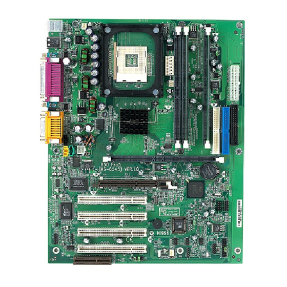
Page 11: Mainboard Layout
JWR3 RIMM1 BATT Winbond AGP Slot W83627HF-AW JBAT1 Intel 82801BA PCI Slot 1 JGS1 PCI Slot 2 JUSB1 JUSB2 (Optional) (Optional) BIOS PCI Slot 3 (Optional) PCI Slot 4 JMDM1 JFP1 SYSFAN JRMS1 (Optional) 850 Pro5 (MS-6545 v1.X) ATX Mainboard... -
Page 12: Quick Components Guide
Introduction Quick Components Guide Component Function Reference JWR1/2/3 ATX power connectors See p. 2-7 JKBMS1 Mouse/keyboard connector See p. 2-9 USB Connectors Connecting to USB devices See p. 2-10 COM A & COM B Serial port connector See p. 2-11 L P T 1 Parallel port connector See p. -
Page 13: Key Features
Chapter 1 Key Features ATX Form Factor CPU: Intel Pentium 4 processor in the 478 pin package ® ® Smart Key - the best solution to prevent unauthorized access to your PC (Optional) USB PC to PC networking function (Optional) Fuzzy Logic 3 Live BIOS / Live Driver CMI8738/PCI-6ch supports 2/4/6 ch. -
Page 14: Msi Special Features
Introduction MSI Special Features T.O.P Tech™ The T.O.P Tech is an extended sensing device that can 100% accu- rately detect the CPU’s temperature. You can find out the temperature on BIOS setup menu. The PC Alert also provides the information. -
Page 15: Pc Alert™ Iii
Chapter 1 PC Alert™ III The PC Alert III is a utility you can find in the CD-ROM disk. The utility is just like your PC doctor that can detect the following PC hardware status during real time operation: * monitor CPU & system temperatures * monitor fan speed(s) * monitor system voltage * monitor chassis intrusion... - Page 16 Introduction Features: Network Management - Monitoring & remote control Basic System Utilities - Scandisk & Defragment to maintain your HDD 3D Graphics Design - Enables a more friendly user interface Sofware Utilities - SoftCooler Optimized Cooling...
-
Page 17: D-Led™ & D-Bracket™ (Optional)
Chapter 1 D-LED™ & D-Bracket™ (Optional) The D-LED™ uses graphic signal display to help users understand their system. Four LEDs embedded in the mainboard provide up to 16 combinations of signals to debug the system. The 4 LEDs can debug all problems that fail the system, such as VGA, RAM or other failures. - Page 18 Introduction D-LED D-Bracket Description Processor Initialization - This will show information regarding the processor (like brand name, system bus, etc…) Testing RTC (Real Time Clock) Initializing Video Interface - This will start detecting CPU clock, checking type of video onboard. Then, detect and initialize the video adapter. BIOS Sign On - This will start showing information about logo, processor brand name, etc….
-
Page 19: Fuzzy Logic™ Iii
Chapter 1 Fuzzy Logic™ III The Fuzzy Logic™ III utility allows users to overclock the CPU FSB (Front Side Bus) frequency in the Windows environment. Select the CPU fre- quency you prefer and click Go to apply the frequency or click Save allowing the system to run at the specified frequency each time when the system is powered on. -
Page 20: Live Bios™/Live Driver
After installation, the “MSI Live Update Series” icon (as the right view) will appear on the screen. Double click the “MSI Live Update Series” icon, and the following screen will appear. Four buttons are placed on the left column of the screen. Click the desired button to start the update process. -
Page 21: Chapter 2. Hardware Setup
Hardware Setup C h a p t e r Hardware Setup This chapter provides you with the information about hardware setup procedures. While doing the installation, be careful in holding the components and follow the installation procedures. For some components, if you install in the wrong orientation, the components will not work properly. -
Page 22: Central Processing Unit: Cpu
Chapter 2 Central Processing Unit: CPU ® ® The mainboard supports Intel Pentium 4 processor in the 478 pin package. The mainboard uses a CPU socket called PGA478 for easy CPU installation. When you are installing the CPU, make sure the CPU has a heat sink and a cooling fan attached on the top to prevent overheating. -
Page 23: Installing The Cpu Fan
Hardware Setup Installing the CPU Fan As processor technology pushes to faster speeds and higher performance, thermal managment becomes increasingly important. To dissi- pate heat, you need to attach the CPU cooling fan and heatsink on top of the CPU. Follow the instructions below to install the Heatsink/Fan: Locate the CPU and its retention Position the heatsink onto the reten- mechanism on the motherboard. -
Page 24: Cpu Core Speed Derivation Procedure
Chapter 2 C o n n e ct th e f a n p o w e r cab l e f r om th e moun t ed f a n to th e 3- p i n f a n p o w e r con n e ctor on th e b o ard. -
Page 25: Memory Installation
Hardware Setup Memory Installation The mainboard provides 4 gold-lead sockets for 184-pin RIMM modules. To operate properly, at least two RIMM modules must be installed. The mainboard supports the memory size up to 2 GB. RIMM Slots (RIMM 1~4) RIMM1 Memory Population Rules Support RIMM only. -
Page 26: Installing Rimm Modules
Chapter 2 Installing RIMM Modules You can install two or four RIMM modules in the following combination: DIMM Socket Memory Module Total Memory Socket 1 32MB, 64MB, 128MB, 32MB ~ 512MB (Bank 0 & Bank 1) 256MB, 512MB Socket 2 32MB, 64MB, 128MB, 32MB ~ 512MB (Bank 2 &... -
Page 27: Power Supply
Hardware Setup Power Supply The mainboard supports ATX power supply for the power system. Be- fore inserting the power supply connector, always make sure that all compo- nents are installed properly to ensure that no damage will be caused. ATX 20-Pin Power Connector: JWR1 This connector allows you to connect to an ATX power supply. -
Page 28: Atx 12V Power Connector: Jwr3
Chapter 2 ATX 12V Power Connector: JWR3 Attaching the ATX power supply to the connector help offer sufficient voltage to Pentium 4 CPU. This power connector also supports instant power on function. JWR3 SIGNAL ATX 5V/3V Power Connector: JWR2 The mainboard provides an extra 5V/3V power connector for you to connect to the ATX power supply. -
Page 29: Back Panel
Hardware Setup Back Panel The Back Panel provides the following connectors: Parallel Midi/Joystick Mouse Keyboard COM A COM B L-out L-in MIC Mouse Connector: JKBMS1 ® The mainboard provides a standard PS/2 mouse mini DIN connector for ® ® attaching a PS/2 mouse. -
Page 30: Keyboard Connector: Jkbms1
Chapter 2 Keyboard Connector: JKBMS1 ® The mainboard provides a standard PS/2 keyboard mini DIN connector for attaching a PS/2 ® keyboard. You can plug a PS/2 ® keyboard directly into this connector. Pin Definition SIGNAL DESCRIPTION Keyboard DATA Keyboard DATA No connection Ground Keyboard Clock... -
Page 31: Serial Port Connector: Com A & Com B
Hardware Setup Serial Port Connector: COM A & COM B The mainboard offers two 9-pin male DIN connectors for serial port COM A and COM B. The ports are 16550A high speed communication ports that send/receive 16 bytes FIFOs. You can attach a serial mouse or other serial devices directly to them. -
Page 32: Parallel Port Connector: Lpt1
Chapter 2 Parallel Port Connector: LPT1 The mainboard provides a 25-pin female centronic connector for LPT. A parallel port is a standard printer port that supports Enhanced Parallel Port (EPP) and Extended Capabilities Parallel Port (ECP) mode. Pin Definition SIGNAL DESCRIPTION STROBE Strobe... -
Page 33: Connectors
Hardware Setup Connectors The mainboard provides connectors to connect to FDD, IDE HDD, case, modem, LAN, USB Ports, IR module and CPU/System FAN. Floppy Disk Drive Connector: FDD1 The mainboard provides a standard floppy disk drive connector that supports 360K, 720K, 1.2M, 1.44M and 2.88M floppy disk types. FDD1 Remote Power On/Off Switch Connector: JRMS1 Connect to a 2-pin push button switch. -
Page 34: Hard Disk Connectors: Ide1 & Ide2
Chapter 2 Hard Disk Connectors: IDE1 & IDE2 The mainboard has a 32-bit Enhanced PCI IDE and Ultra DMA 33/66/100 controller that provides PIO mode 0~4, Bus Master, and Ultra DMA/33/66/100 function. You can connect up to four hard disk drives, CD-ROM, 120MB Floppy (reserved for future BIOS) and other devices. -
Page 35: Front Panel Connector: Jfp1 Or J23 (Optional Intel Spec)
Hardware Setup Front Panel Connector: JFP1 or J23 (Optional Intel spec) This connector is for electrical connection to the front panel switches and LEDs. Keylock HDD LED Buzzer (short pin) Power Speaker Power Switch Reset Switch JFP1 (Optional Intel spec) J23 Pin Definition SIGNAL DESCRIPTION... -
Page 36: Cd-In/Aux-In/Modem-In Connector: Jcd1/Jaux1/Jphn1
Chapter 2 CD-In/Aux-In/Modem-In Connector: JCD1/JAUX1/JPHN1 JCD1 connector is for CD-ROM audio connector. JAUX1 connector is for DVD add-on card with Line-in connector. JPHN1 connector is for modem with internal audio connector. JCD1 JAUX1 Mono_Out Phone_In JPHN1 Note: Mono_Out is connected to the Modem speaker-out connector. Phone_In is connected to the Modem Microphone-In connector. -
Page 37: Fan Power Connectors: Cpufan/Sysfan/Psfan
Hardware Setup Fan Power Connectors: CPUFAN/SYSFAN/PSFAN The CPUFAN (processor fan), SYSFAN (system fan) and PSFAN1 (power supply fan) support system cooling fan with +12V. It supports three-pin head connector. When connecting the wire to the connectors, always take note that the red wire is the positive and should be connected to the +12V, the black wire is Ground and should be connected to GND. -
Page 38: Wake On Ring Connector: Jmdm1
Chapter 2 Wake On Ring Connector: JMDM1 This connector allows you to connect to a modem card with Wake On Ring function. The connector will power up the system when a signal is re- ceived through the modem card. MDM_WAKEUP 5VSB JMDM1 Note: Modem wake-up signal is active “low”. -
Page 39: Irda Infrared Module Connector: J18
Hardware Setup IrDA Infrared Module Connector: J18 This connector allows you to connect to an IrDA Infrared module. You must configure the setting through the BIOS setup to use the IR function. Signal IRRX IRTX Chassis Intrusion Switch Connector: J12 The connector is connected to a 2-pin chassis switch. -
Page 40: Front Panel Audio Connector: J22 (Optional Intel Spec)
Chapter 2 Front Panel Audio Connector: J22 (Optional Intel spec) This connector allows you to connect to the front panel audio. (Optional Intel spec) Pin Definition SIGNAL DESCRIPTION AUD_MIC Front panel microphone input signal AUD_GND Ground used by analog audio circuits AUD_MIC_BIAS Microphone power AUD_VCC... -
Page 41: Front Usb Connectors: Jusb1 & Jusb2
Depending on users’ request, the mainboard can provide ONE or TWO USB (Universal Serial Bus) pin headers that allow you to connect optional USB ports for front panel. Option 1 JUSB1: MSI spec ® JUSB2: Intel spec/compliant with Intel I/O Connectivity Design Guide... - Page 42 Chapter 2 Option 2 JUSB1: USB PC to PC networking function JUSB1 (USB PC to PC (USB 1.1) Networking) JUSB1 Pin Definition Description Description USB0- USB0+ USB1+ USB1- 2-22...
- Page 43 Hardware Setup Note: USB PC to PC Networking feature allows users to transfer and receive data from other computers or share system resources with others without using any network adapter. See below for instructions. To Attach the USB PC to PC cable Check whether the package includes the following items.
- Page 44 Chapter 2 Connect your PC to another PC via USB PC to PC cable. The transfer rate will run at USB 1.1 speed (12Mbps/s). Connect to the B Connect to the Type Connector USB 1.1 port of on your PC another PC B Type Connector For more information on USB PC to PC Networking function, refer...
-
Page 45: D-Bracket™ Connector: J24
Hardware Setup D-Bracket™ Connector: J24 The mainboard comes with a J24 connector for you to connect to D- Bracket™. D-Bracket™ is a USB Bracket integrating four LEDs whose func- tions are similar to D-LED™ and allows users to identify system problem through 16 various combinations of LED signals. - Page 46 Chapter 2 D-Bracket™ with one USB PC to PC port and one regular USB port Connected to J24 Connected to JUSB1 pin header which is implemented with USB PC To PC Networking function D-Bracket™ with two regular USB ports Connected to J24 Connected to JUSB1 or JUSB2 pin header which DOES NOT support USB PC To PC networking function...
-
Page 47: Jumpers
Hardware Setup Jumpers The motherboard provides one jumper for you to set the computer’s function. This section will explain how to change your motherboard’s function through the use of the jumper. Clear CMOS Jumper: JBAT1 There is a CMOS RAM on board that has a power supply from external battery to keep the data of system configuration. -
Page 48: Rdram Over Voltage Jumper: J20
Chapter 2 RDRAM Over Voltage Jumper: J20 The jumper is used to set the RDRAM voltage for overclocking purpose. Normal Over Voltage Over Voltage (2.5V) (2.58V) (2.68V) Over Voltage This motherboard is designed to support over voltage. However, please make sure your components are able to WARNING! tolerate such abnormal setting, while doing over voltage. -
Page 49: Clear Bios Password Jumper: J17
Hardware Setup Clear BIOS Password Jumper: J17 The jumper is used to clear the BIOS password. To clear the password, open the jumper and restart your computer. Normal Clear BIOS Flash Jumper: J16 This jumper is used to lock or unlock the boot block area on BIOS. When unlocked, the BIOS boot block area can be updated. -
Page 50: Slots
Chapter 2 Slots The motherboard provides four 32-bit Master PCI Bus Slots, one AGP and one CNR slot. AGP Slot PCI Slots CNR Slot AGP (Accelerated Graphics Port) Slot The AGP slot allows you to insert the AGP graphics card only. AGP is an interface specification designed for the throughput demands of 3D graphics. -
Page 51: Pci Interrupt Request Routing
Hardware Setup PCI Interrupt Request Routing The IRQ, abbreviation of interrupt request line and pronounced I-R-Q, are hardware lines over which devices can send interrupt signals to the microprocessor. The PCI IRQ pins are typically connected to the PCI bus as follows: Order 1 Order 2... -
Page 52: Chapter 3. Award ® Bios Setup
® AWARD BIOS Setup Chapter 3. AWARD BIOS Setup ® AWARD BIOS Setup ® The mainboard uses AWARD BIOS ROM that provides a Setup utility ® for users to modify the basic system configuration. The information is stored in a battery-backed CMOS RAM so it retains the Setup information when the power is turned off. -
Page 53: Entering Setup
Chapter 3 Entering Setup Power on the computer and the system will start POST (Power On Self Test) process. When the message below appears on the screen, press <DEL> key to enter Setup. Press DEL to enter SETUP If the message disappears before you respond and you still wish to enter Setup, restart the system by turning it OFF and On or pressing the RESET button. -
Page 54: Getting Help
® AWARD BIOS Setup Getting Help After entering the Setup menu, the first menu you will see is the Main Menu. Main Menu The main menu lists the setup functions you can make changes to. You can use the control keys ( ↑↓ ) to select the item. The on-line description of the high- lighted setup function is displayed at the bottom of the screen. -
Page 55: The Main Menu
Chapter 3 The Main Menu Once you enter Award BIOS CMOS Setup Utility, the Main Menu (Figure 1) ® will appear on the screen. The Main Menu allows you to select from twelve setup functions and two exit choices. Use arrow keys to select among the items and press <Enter>... - Page 56 ® AWARD BIOS Setup PC Health Status This entry shows your PC health status. Frequency/Voltage Control Use this menu to specify your settings for frequency/voltage control. High System Performance Use this menu to load the BIOS values for the best system performance, but the system stability may be affected.
-
Page 57: Standard Cmos Features
Chapter 3 Standard CMOS Features The items in Standard CMOS Features Menu are divided into 10 categories. Each category includes no, one or more than one setup items. Use the arrow keys to highlight the item and then use the <PgUp> or <PgDn> keys to select the value you want in each item. - Page 58 ® AWARD BIOS Setup ing items. Enter the information directly from the keyboard. This information should be provided in the documentation from your hard disk vendor or the system manufacturer. If the controller of HDD interface is SCSI, the selection shall be “None”. If the controller of HDD interface is CD-ROM, the selection shall be “None”.
-
Page 59: Advanced Bios Features
Chapter 3 Advanced BIOS Features Virus Warning The setting is to set the virus warning feature for IDE hard disk boot sector protection. If the function is enabled and any attempt to write data into this area is made, BIOS will display a warning message on the screen and beep. Setting options: Disabled, Enabled. - Page 60 ® AWARD BIOS Setup computer. When setting the item to Enabled, BIOS will shorten or skip some check items during POST. Setting options: Enabled, Disabled. First/Second/Third Boot Device The items allow you to set the sequence of boot devices where BIOS attempts to load the disk operating system.
- Page 61 Chapter 3 Normal is selected, A20 is controlled by a keyboard controller or chipset hardware. Typematic Rate Setting This setting is used to enable or disable the typematic rate setting including Typematic Rate & Typematic Delay. Typematic Rate (Chars/Sec) After Typematic Rate Setting is enabled, this item allows you to set the rate (characters/second) at which the keys are accelerated.
- Page 62 ® AWARD BIOS Setup Report No FDD For WIN 95 For compatibility with Windows 95 logo certification, select Yes to release IRQ6 when the system contains no floppy drive. When this setting is set to Yes, users have to select Disabled for the Onboard FDC Controller in the Inte- grated Peripherals menu.
-
Page 63: Advanced Chipset Features
Chapter 3 Advanced Chipset Features The Advanced Chipset Features Setup option is used to change the values of the chipset registers. These registers control most of the system options in the computer. Choose the “ADVANCED CHIPSET FEATURES” from the Main Menu and the following screen will appear. - Page 64 ® AWARD BIOS Setup memory area, a system error may result. Setting options: Enabled, Disabled. Delayed Transaction The chipset has an embedded 32-bit posted write buffer to support delayed transactions cycles so that transactions to and from the ISA bus are buffered and PCI bus can perform other transactions while the ISA transaction is underway.
-
Page 65: Integrated Peripherals
Chapter 3 Integrated Peripherals On-Chip Primary/Secondary PCI IDE The integrated peripheral controller contains an IDE interface with support for two IDE channels. Choose Enabled to activate each channel separately. IDE Primary/Secondary Master/Slave PIO The four items allow you to set a PIO (Programmed Input/Output) mode for each of the four IDE devices that the onboard IDE interface supports. - Page 66 ® AWARD BIOS Setup USB Controller Select Enabled if your system contains a Universal Serial Bus (USB) controller and you have USB peripherals. Setting options: Enabled, Disabled. USB Keyboard Support Set to Enabled if your need to use an USB keyboard in the operating system that does not support or have any USB driver installed, such as DOS and SCO Unix.
- Page 67 Chapter 3 system. Settings: Password, Hot KEY, Mouse Left, Mouse Right, BUTTON ONLY and Keyboard 98. KB Power ON Password If POWER ON Function is set to Password, then you can set a password in the field for the PS/2 keyboard to power on the system. Hot Key Power ON If POWER ON Function is set to Hot KEY, you can assign a hot key combina- tion in the field for the PS/2 keyboard to power on the system.
- Page 68 ® AWARD BIOS Setup options: Full, Half. Under Full Duplex mode, synchronous, bi-directional trans- mission/reception is allowed. Under Half Duplex mode, only asynchronous, bi- directional transmission/reception is allowed. Use IR Pins Please consult your IR peripheral documentation to select the correct setting of the TxD and RxD signals.
- Page 69 Chapter 3 interrupts occurs. Available settins are: Leaves the computer in the power off state. Reboots the computer. Former-Sts Restores the system to the status before power failure or interrupt occurs. Game Port Address/Midi Port Address This setting disables or assigns an address for the onboard game/midi port. Midi Port IRQ This setting specifies an IRQ for the onboard midi port.
-
Page 70: Power Management Setup
® AWARD BIOS Setup Power Management Setup The Power Management Setup allows you to configure you system to most effectively save energy while operating in a manner consistent with your own style of computer use. ACPI Suspend Type This item specifies the power saving modes for ACPI function. Options are: S1/POS The S1 sleep mode is a low power state. - Page 71 Chapter 3 to these modes: Suspend Mode and HDD Power Down. There are three op- tions for power management: Min Saving Minimum Power Management. Suspend Mode = 1 Hour, and HDD Power Down = 15 Min. Max Saving Maximum Power Management. Suspend Mode = 1 Min, and HDD Power Down = 1 Min.
- Page 72 ® AWARD BIOS Setup HDD Power Down If HDD activity is not detected for the length of time specified in this field, the hard disk drive will be powered down while all other devices remain active. Settings are Disabled and 1 through 15 Min. Soft-Off by PWR-BTTN This feature allows users to configure the power button function.
- Page 73 Chapter 3 Reload Global Timer Events: Primary IDE 0/1, Secondary IDE 0/1, FDD/ COM/LPT Port, PCI PIRQ [A-D]# Global Timer Events are I/O events whose occurrence can prevent the system from entering a power saving mode or can awaken the system from such a mode.
-
Page 74: Pnp/Pci Configurations
® AWARD BIOS Setup PNP/PCI Configurations This section describes configuring the PCI bus system. PCI, or Personal Com- puter Interconnect, is a system which allows I/O devices to operate at speeds nearing the speed the CPU itself uses when communicating with its own spe- cial components. - Page 75 Chapter 3 Press <Enter> and you will enter the sub-menu of the items. IRQ Resources list IRQ 3/4/5/7/9/10/11/12/14/15 for users to set each IRQ a type depending on the type of device using the IRQ. Settings are: PCI Device For Plug & Play compatible devices designed for PCI bus architecture.
-
Page 76: Pc Health Status
® AWARD BIOS Setup PC Health Status This section shows the status of your CPU, fan, warning for overall system status. Chassis Intrusion Detect Set this option to enable, reset, or disable the chassis intrusion detector. Dur- ing Enabled, any intrusion on the system chassis will be recorded. The next time you turn on the system, it will show a warning message. -
Page 77: Frequency/Voltage Control
Chapter 3 Frequency/Voltage Control CPU Clock Ratio This setting controls the multiplier that is used to determine the internal clock speed of the processor relative to the external or motherboard clock speed. CPU Vcore Select This setting allows you to set the CPU core voltage. Setting options: Default, +25mV, +50mV, +75mV, +100mV. - Page 78 ® AWARD BIOS Setup 25MHz (with a 1GHz CPU) which may just cause your overclocked processor to lock up. CPU Clock This setting specifies the clock frequency of CPU host bus (FSB) and provides a method for end-users to overclock the processor accordingly. 3-27...
-
Page 79: High System Performance
Chapter 3 High System Performance This option on the main menu allows users to restore all the BIOS settings to the default High Performance values. The High Performance Defaults are the default values set by the mainboard manufacturer specifically for maximal sys- tem performance but will probably cause a stability issue. -
Page 80: Load Optimized Defaults
® AWARD BIOS Setup Load Optimized Defaults This option on the main menu allows users to restore all the BIOS settings to the default Optimized values. The Optimized Defaults are the default values also set by the mainboard manufacturer for both optimized and stable perform- ance of the mainboard. -
Page 81: Set Supervisor/User Password
Chapter 3 Set Supervisor/User Password When you select this function, a message as below will appear on the screen: Type the password, up to eight characters in length, and press <Enter>. The password typed now will clear any previously set password from CMOS memory. - Page 82 ® AWARD BIOS Setup entry to Setup. If set to Setup, password prompt only occurs when trying to enter Setup. About Supervisor Password & User Password: Supervisor password : Can enter and change the settings of the setup menus. User password: Can only enter but do not have the right to change the settings of the setup menus 3-31...
-
Page 83: Save & Exit Setup
Chapter 3 Save & Exit Setup When you want to quit the Setup menu, you can select this option to save the changes and quit. A message as below will appear on the screen: Typing “Y” will allow you to quit the Setup Utility and save the user setup changes to RTC CMOS. -
Page 84: Exit Without Saving
® AWARD BIOS Setup Exit Without Saving When you want to quit the Setup menu, you can select this option to abandon the changes. A message as below will appear on the screen: Typing “Y” will allow you to quit the Setup Utility without saving any changes to RTC CMOS. -
Page 85: Appendix A: Msi Smart Key
MSI Smart Key Appendix A: MSI Smart Key MSI Smart Key If security is important to you, the MSI Smart Key is the best solu- tion to prevent your data in the computer from being accessed by un- authorized people. -
Page 86: Installing Msi Smart Key
BIOS will detect it when the system boots up, and you have to enabled/ disabled this function. Furthermore, you should install the dedicated software application in the operating system, which is provided by MSI, to obtain the overall protection on your system. The following sections will provide the detailed instructions for the BIOS setup and software installation. -
Page 87: Using Msi Smart Key
The message as below appears on the screen asking you to enable or disable the key: Welcome to MSI Smart Key, please press “Y” to begin, press “N” to exit Type <Y> to enable it; type <N> to disable it and bypass the BIOS to enter the operating system. - Page 88 Note: 1. You should firmly remember the password you set; if the Smart Key is lost, you can get a new key from MSI, and turn on the computer with the original password. 2. To avoid the password from being forgotten, we provide the table below for you to keep note in this guide.
- Page 89 The message as below appears on the screen asking you to enable or disable the key: If you want to disable MSI Smart Key, please press “Y”, or press “N” to exit Type <Y> to disable it; type <N> to keep the function enabled and enter the operating system.
- Page 90 Appendix A Boot up with no key /wrong key/new key installed Once the MSI Smart Key is enabled, always keep the key inserted in the computer. If the key is unplugged, the other user can not access the computer. The message as below appears during the system boot-...
- Page 91 MSI Smart Key Software Setup When the Smart Key is inserted into your computer and the soft- ware application is installed in the operating system, it will serve as a safeguard for your system. When the key is unplugged, the operating system will enter protection status immediately and the mouse and keyboard will be locked;...
- Page 92 Appendix A When the Software License Agreement window appears on the screen, press [ Yes ] to continue. Click here Choose the folder to install the software in your computer; simply press [ Next > ] to install it in the default folder. Default folder When the installation is completed, restart the computer as instructed.
- Page 93 MSI Smart Key Using the Software Application When the program is installed in the operating system, it will embed in the system tray and show an icon as below: Smart Key icon Note: When the Smart Key function is disabled in BIOS, this program will not be launched in the operating system.
- Page 94 Appendix A Security Setting This option allows you to logon to Windows automatically. Select the “Auto Login” item and check the “Auto Logon to Windows” item in the Setting Page field to enable the function. Once the function is enabled and set properly, you do not have to type the user’s name and password everytime when entering Windows.
- Page 95 Smart Key is unplugged and the system locked. You can set the monitor to display: a) blank screen b) the retaining screen when the system locked c) MSI Logo The default setting is to show MSI Logo. A-11...
- Page 96 Appendix A Press the “Apply Changes” button to enable the option you choose. Click here Press the “bulb” button at the right-bottom to hide the program in the system tray and keep on monitoring the system. Click here Press the “door” button at the right-bottom to exit the program. Click here A-12...
- Page 97 MSI Smart Key Removing the Software Application To remove the program, follow the steps below: Click and choose Settings ¡ ÷ Control Panel; double- click the Add/Remove Programs item to open the “Add/Remove Programs Properties” window. Choose this Click here Select the “SmartKey”...
-
Page 98: Appendix B: Using 4-/6-Channel Audio Function
Using 4-/6-channel Audio Function Appendix B: Using 4-/6-channel Audio Function Using 4-/6-channel Audio Function The mainboard comes with C-Media 6-channel audio function, which allows you to attach 4 or 6 speakers for better space sound effect. The section will tell you how to activate 4-/6-channel audio function. This section includes the following topics: Installing C-Media Drivers Hardware Configuration... -
Page 99: Installing C-Media Drivers
Appendix B Installing C-Media Drivers The mainboard is able to transform the audio connectors on the back panel from 2-channel to 4-/6-channel. To use the function, you need to install the C- Media drivers. To install C-Media drivers: Insert the companion CD into the CD-ROM drive. The setup screen will automatically appear. -
Page 100: Software Configuration
Using 4-/6-channel Audio Function Software Configuration To have 4-/6-channel audio work, you must set appropriate configuration in the C-Media software application. To set the multi-channel configuration: Click the C-Media Mixer icon from the window tray on the bottom. The following screen appears. Click the indicated button. Click here The “Advanced”... - Page 101 USB PC to PC Networking Function Appendix C. USB PC to PC Networking Function USB PC to PC Networking Function (Optional) USB PC to PC is the best solution for providing the easiest network connection service to you. By connecting multiple PCs through USB PC to PC port, you can build up a local area network without any network adapter.
- Page 102 Appendix C Installing GeneLink™ LAN Driver Before you use the function, you need to install the GeneLink™ LAN Driver to all PCs connected via USB PC to PC cables. Step 1. Installing driver 1. Insert the driver CD and click “USB PC to PC” button to install the driver. 2.
-
Page 103: Appendix C. Usb Pc To Pc Networking Function
USB PC to PC Networking Function Notice: 1. You should use the same network protocol (TCP/IP, NetBEUI or IPX) for connecting GeneLink LAN to existing Home/Office LAN. 2. If you’ve already configured your [IPX/SPX] and [Client for Netware Networks] before installing GeneLink driver, we strongly recommend that you should also install Software Router while installing GeneLink... -
Page 104: Using Usb Pc To Pc Networking Function
Appendix C Using USB PC to PC Networking Function How to share your files, folders, drives and printers Go to the file, folder, drive or printer that you want to share. Right click your mouse pointer on the resource you want to share, you’ll see a POP-UP Menu. - Page 105 USB PC to PC Networking Function In “Sharing” tag, select “Share As”. Enter a name to help others recognize your sharing file or device (optional). Select “Access Type”. If you select “ Depend on Password”, your need to assign an access password for this device. Click “OK”...
- Page 106 Appendix C Connecting to Internet through USB PC to PC & Office/Home LAN If you would like to access Internet resources through USB PC to PC, here are some things you should notice: You must define which computer should install GeneLink Software Router.
- Page 107 USB PC to PC Networking Function - Click on “Properties”, you’ll see another menu. - Choose TCP/IP in Configuration tag, and then press “Proper- ties” button. You’ll see “TCP/IP Properties” menu.
- Page 108 Appendix C - Now you need to navigate between “IP Address”, “Gateway”, and “DNS Configuration” tags to specify “IP Address”, “Subnet Mask”, “Gateway” and “DNS Server”. If you don’t know their values, pleases consult your Network Administrator. - Press “OK” button to go back to “Network” pop-up menu. Choose “Identification”...
- Page 109 USB PC to PC Networking Function SPECIAL NOTICE for those users who have already installed Network Adapter in their system: If you’ve already configured your [IPX/SPX] and [Client for Netware Networks] before installing GeneLink driver, we strongly recommend that you should also install Software Router when you install GeneLink driver into your system.
- Page 110 Appendix C Connecting to internet through USB PC to PC & remote modem If there is no existing Office/Home LAN and your computer does not have a modem, you still can connect USB PC to PC to internet through another computer with a modem installed.
- Page 111 USB PC to PC Networking Function “Communications”. The “Communications” window appears. Check “Internet Connection Sharing” and click “OK”. The “Home Networking Wizard” starts. Click “Next”. C-11...
- Page 112 Appendix C Click “Adirect connection to my ISP using the following device”, and select “GeneLink Network Adapter” from the pull- down menu. Click “Next”. Note: For the computer with a modem installed, you need to select “My Connection” instead of “GeneLink Network Adapter”...
- Page 113 USB PC to PC Networking Function Click “Finish.” Restart the computer. Note: In Windows® 98SE, you can access internet through the shared connection of another computer, but it is unable for you to control the remote modem. However, in Windows® ME, you are allowed to dial the remote modem of another computer using the dialing program built in Windows®.
-
Page 114: Glossary
Glossary Glossary Glossary ACPI (Advanced Configuration & Power Interface) This power management specification enables the OS (operating system) to control the amount of power given to each device attached to the computer. Windows 98/98SE, Windows 2000 and Windows ME can fully support ACPI to allow users managing the system power flexibly. AGP (Accelerated Graphics Port) A new, high-speed graphics interface that based on PCI construction and designed especially for the throughput demands of 3-D graphics. - Page 115 Glossary example, a modem chipset contains all the primary circuits for transmitting and receiving data; a PC chipset provides the electronic interfaces between all subsystems. CMOS (complementary metal-oxide semiconductor) CMOS is a widely used type of semiconductor, which features high speed and low power consumption.
- Page 116 Glossary ECC Memory (error correcting code memory) A type of memory that contains special circuitry for testing the accuracy of data and correcting the errors on the fly. IDE (Integrated Drive Electronics) A type of disk-drive interface widely used to connect hard disks, CD-ROMs and tape drives to a PC, in which the controller electronics is integrated into the drive itself, eliminating the need for a separate adapter card.
- Page 117 Glossary PnP (Plug and Play) A set of specifications that allows a PC to configure itself automatically to work with peripherals. The user can "plug" in a peripheral device and "play" it without configuring the system manually. To implement this useful feature, both the BIOS that supports PnP and a PnP expansion card are required.
Need help?
Do you have a question about the MS-6545 and is the answer not in the manual?
Questions and answers