
Related Manuals for SMC Networks LFE0 Series


Summary of Contents for SMC Networks LFE0 Series
- Page 1 Doc.No.LFE****-OMZ0013 Product Name Flow Monitor Model/ Series/ Product Number LFE0### SMC Corporation...
-
Page 2: Table Of Contents
Contents Safety Instructions Model Indication and How to Order Summary of Product Parts Definition and Terminology Mounting and Installation Installation Wiring Setting the Detected Flow Rate Function Setting Default Setting F 0 Selection of sensor F 1 Setting of OUT1 F 2 Setting of OUT2 F 3 Response Time F10 Sub screen display... -
Page 3: Safety Instructions
Safety Instructions These safety instructions are intended to prevent hazardous situations and/or equipment damage. These instructions indicate the level of potential hazard with the labels of “Caution,” “Warning” or “Danger.” They are all important notes for safety and must be followed in addition to International Standards (ISO/IEC) , and other safety regulations. - Page 4 Safety Instructions Caution The product is provided for use in manufacturing industries. The product herein described is basically provided for peaceful use in manufacturing industries. If considering using the product in other industries, consult SMC beforehand and exchange specifications or a contract if necessary. If anything is unclear, contact your nearest sales branch.
- Page 5 ■Explanation of Symbols S ym b o l Definition Things you must not do. Actual instructions are provided as a drawing or sentence close to this mark. Things you must do Actual instructions are provided as a drawing or sentence close to this mark. ■...
- Page 6 Caution Do not touch the terminals and connectors while the power is on. Otherwise electric shock, malfunction or damage to the switch can result. Do not touch Do not touch the piping joint or piping when hot fluid is used. It may lead to burn.
- Page 7 ● Product handling * Installation - Tighten to the specified tightening torque. If the tightening torque is exceeded, the mounting screws, brackets and product may be damaged. Insufficient torque can cause displacement of the product from its proper position and the looseness of the mounting screws. - If a commercially available switching power supply is used, be sure to ground the frame ground (FG) terminal.
- Page 8 Operating environment - Do not use the product in an environment where the product is constantly exposed to water splashes. Otherwise failure or malfunction can result. Take measures such as using a cover. - Do not use in an environment where the product could be exposed to corrosive gas or liquids. Otherwise damage to the internal parts can result, causing malfunction.
- Page 9 * Adjustment and Operation - Check the load status before turning the power supply on. - Do not short-circuit the load. Although error is displayed when the product load has a short circuit, generated over current may lead to the damage of the product.
-
Page 10: Model Indication And How To Order
Model Indication and How to Order □□ □□□ LFE0 Remote type monitor Option2(Connector) Output Specifications Symbol OUT1 OUT2 Analogue 1 to 5V Analogue 4 to 20mA Lead wire Option1(Panel type) Display unit Instantaneous Accumulated Symbol flow flow L/min gal/min *G: Made to order Reference: 1[L/min] 0.2642[gal/min]... -
Page 11: Summary Of Product Parts
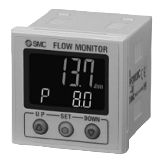
Summary of Product Parts Front Units indication Description Function Main screen (2 color display) Displays the flow value, setting mode and error codes. Displays the output status of OUT1 and OUT2. LED is ON (Orange) when Output display (Indicator light) OUT1 is ON. -
Page 12: Definition And Terminology
■ Definition and Terminology Term Meaning The total amount of fluid that has passed through the device. If an instantaneous flow of Accumulated flow 10 L/min lasts for 5 minutes, the accumulated flow will be 10 x 5=50 L. Accumulated pulse A type of output where a pulse is generated every time a predefined accumulated flow output passes.It is possible to calculate the total accumulated flow by counting the pulses. - Page 13 Term Meaning Power saving mode Number display is turned off to reduce power consumption. Reproducibility of the display or analogue output value, when the measured quantity is Repeatability repeatedly increased and decreased. Response time The delay time until the set value reaches 63% in relation to the step input. The range of ON/OFF threshold values that can be set for those products with a switch Set point range output.
-
Page 14: Mounting And Installation
Mounting and Installation ■ Installation Mounting by panel mount adapter Fix the panel mount adapter to the controller by the mounting screws M3 x 8L (2 pcs.). Panel mount adapter (Part number: ZS-26-B) Front protective cover (Part number: ZS-26-01) *1: The panel mount adapter can be rotated through 90 degrees for mounting. The panel mount adapter should be fixed firmly with screws. -
Page 15: Wiring
■ Wiring Connecting and disconnecting of the sensor connector and power supply/output connector When connecting, insert the connectors straight into the body until it clicks. ・When removing the connector, press down the lever to release the hook from the housing and pull the connector straight out. - Page 16 Wiring of connector Attaching/detaching of the connector should be done while the power supply is turned off. Power lines and high-voltage lines can cause noise. Keep the wiring away from them. Otherwise, malfunction may result due to noise. Ensure that the FG terminal is connected to ground when using a commercially available switch-mode power supply.
- Page 17 Internal Circuit and Wiring examples PNP 2 output type NPN 2 output type LFE0A LFE0B Max.28 V, 80 mA Max.80 mA Internal voltage drop 1 V max. Internal voltage drop 1.5 V max. NPN + Analogue voltage output type NPN + Analogue current output type LFE0C LFE0D Max.28 V, 80 mA...
-
Page 18: Setting The Detected Flow Rate
Setting the Detected Flow Rate Measurement mode Measurement mode is the condition where the flow is detected and displayed, and the switch function is operating. This basic mode is the beginning from which you can proceed with changing the setting or setting other functions. - Page 19 <Simple setting> (1) Press the button once in measurement mode. [P_1] or [n_1] and the set value are displayed alternately. Normal output Displayed in turn Reversed output (2) Press the button to change the set value (P_1/n_1). button is to increase and the button is to decrease the set value.
-
Page 20: Function Setting
Function Setting Function selection mode In measurement mode, press the button for 2 seconds or longer to display [F 0] on the main screen. In this mode, you can change the function settings. Display the function number [F□□]. Press and hold the button for 2 seconds or longer in the function selection mode to return to measurement mode. - Page 21 # Other parameter setting Item Page Default setting [F 3] Response time Page 36 1 sec. [F10] Sub screen Page 37 Display of set value [F20] External input Page 41 Free range analogue output for instantaneous flow: [F22] Analogue output Page 42 [F30] Accumulated flow value hold Page 44...
-
Page 22: F 0 Selection Of Sensor
■ [F 0] Selection of sensor Select the connected sensor before use. In measurement mode, when the button is pressed for 2 seconds or longer, [F 0] is displayed. The sub screen displays [RANGE] and the currently selected flow rate alternately. Press the button. -
Page 23: F 1 Setting Of Out1
■ [F 1] Setting of OUT1 Set the output mode of OUT1. <Function setting Flowchart> 1.Selection of output mode Window Accumulated Accumulated Hysteresis comparator output pulse ACCUMU 2. Setting of reversed output 1_P/1_N(Page 23) 3. Input of set values Setting of Setting of Setting of Add/dEC... - Page 24 <Operation> 1. Selection of output mode Press the button in function selection mode to display [F 1] on the main screen. The sub screen alternately displays [oUt1] and the currently set output mode. Press the button. Sub screen Press the button to select the desired output mode.
- Page 25 3. Input of set values Output mode a. When hysteresis mode is selected The sub screen displays the set value. Change it with button. (When reversed output is selected, the main screen displays [n_1].) Press the button to set. Move on to the setting of hysteresis. The sub screen displays the hysteresis value.
- Page 26 Output mode c. When Accumulated output mode is selected Selection of accumulated increment (addition) or decrement (subtraction) Sub screen Press the button to select the desired output mode (Add/dEC). Press the button to set. Move on to the input of set values. Accumulated increment mode Accumulated decrement mode The sub screen displays...
- Page 27 Setting of the upper 3 digits Press the button for 1 second or longer to stop flashing. The sub screen displays the set value. The left most digit of the set value will start flashing. (The required accumulated value should be input one digit at a time.) Input the value with button.
- Page 28 4. Select display color The display color can be set to change depending upon the status of OUT1. Sub screen ON: Green ON: Red Normally: Red Normally: Green OFF: Red OFF: Green Press the button to select the display color. Press the button to set.
- Page 29 # List of output mode Hysteresis H_1 (H_2) Hysteresis mode Instantaneous flow Window Hysteresis H1(H2) Hysteresis H1(H2) comparator mode Instantaneous flow Accumulated Count up from "0". Turns ON increment when the set value is reached. output mode Return to “0” by reset. Normal output Time Accumulated...
- Page 30 Hysteresis H_1 (H_2) Hysteresis mode Instantaneous flow (n_2) Window Hysteresis H1(H2) Hysteresis H1(H2) comparator mode Instantaneous flow (n2H) (n2L) Accumulated Count up from "0". Turns ON increment when the set value is reached (n2A) Return to “0” by reset. output mode Reversed output Time Accumulated...
-
Page 31: F 2 Setting Of Out2
■ [F 2] Setting of OUT2 Set the output mode of OUT2. The display color is defined by OUT1 and cannot be changed with any OUT2 settings <Function setting Flowchart> 1.Selection of output mode Window Accumulated Accumulated Window Hysteresis Hysteresis comparator output pulse output... - Page 32 <Operation> 1. Selection of output mode Press the button in function selection mode to display [F 2] on the main screen. The sub screen displays [oUt2] and the currently set output mode alternately. *: If OUT2 is not provide, the display will be [---]. Press the button.
- Page 33 3. Input of set values Output mode a. When hysteresis mode is selected The sub screen displays the set value. Change it with button. (When reversed output is selected, the main screen displays [n_2].) Press the button to set. Move on to the setting of hysteresis. The sub screen displays the hysteresis value.
- Page 34 Output mode c. When Accumulated output mode is selected Selection of accumulated increment or decrement Switching of Add/dEC is linked to the setting of OUT1, and cannot be selected. (Refer to page 25) Accumulated increment more Accumulated decrement mode The sub screen displays The sub screen displays the set value.
- Page 35 Output mode e. When hysteresis mode for fluid temperature is selected The sub screen displays the set value. Change it with the button. (When normal output is selected, [P1dH] will be displayed.) Press the button to confirm. Move on to the setting of hysteresis. The sub screen displays the set value.
- Page 36 # List of output modes for fluid temperature -35- No.LFE****-OMZ0013...
-
Page 37: F 3 Response Time
■[F 3] Response Time The response time of the switch output can be set. Appropriate setting of the response time can prevent the switch output from chattering. <Operation> Press the button in function selection mode to display [F 3] on the main screen. The sub screen alternately displays [RES] and the current set value. -
Page 38: F10 Sub Screen Display
■[F10] Sub screen display The sub display indication during measurement mode can be selected from the following: - Set value display: Displays the set value of OUT1 (The set values of OUT2 cannot be displayed.) - Accumulated flow display: Displays the accumulated flow of OUT1 (The accumulated flow of OUT2 cannot be displayed.) - Bottom display: The bottom value of fluid is displayed. - Page 39 <Example of sub screen display> Example of display in measurement mode (for 20L/min type) Set value display mode Main screen Instantaneous flow Hysteresis mode Normal output Sub screen Display of set value(=P_1) Main screen Instantaneous flow Reversed output Sub screen Display of set value(=N_1) Main screen Instantaneous flow...
- Page 40 <Example of sub screen display (continued)> Accumulated value display mode Main screen Instantaneous flow Accumulated increment mode Sub screen Display of accumulated value - The accumulated value increases according to the instantaneous flow. - When the value exceeds 999999L, the higher 3 digits(1.5s) and lower 6 digits(3s) are displayed alternately.
- Page 41 <Example of sub screen display (continued)> Main screen Instantaneous flow Line name display mode Sub screen Display of line name The name of the piping line where the product is installed can be displayed. Refer to [F82] Input of line names on page for how to input the line name (page 47). If a fluid temperature sensor is attached, the fluid temperature can be displayed as well.
-
Page 42: F20 External Input
■ [F20] External input This item is not used for this specification. -41- No.LFE****-OMZ0013... -
Page 43: F22 Analogue Output In Free Range
■ [F22] Analogue output in free range This function can be used only when the optional analogue output is present. If the optional temperature sensor is fitted, the analogue output of fluid temperature can be selected. The maximum value of analogue outputs can be set as any flow rate value within the rated range. <Operation>... - Page 44 Press the button. Use the buttons to enter the flow value that will generate 5 V or 20 mA. The entered flow value can be in the range: 10% rated flow, Sub screen to the upper display limit. Flow rate[L/min] 20L/min (Analogue 1-5V) Press the button to set.
-
Page 45: F30 Accumulated Flow Value Hold
■[F30] Accumulated flow value hold The default setting is to clear the accumulated flow value when the power supply is turned off. This function enables the accumulated flow value to be stored in permanent memory every 2 or 5 minutes. The maximum writable limit of the memory device is 1 million cycles. -
Page 46: F80 Power Saving Mode
■[F80] Power saving mode The display can be turned off to reduce power consumption. (Reduced by approx. 12%) When this function is selected, if no buttons are pressed for 30 seconds, the display will enter power saving mode. In the default setting, power saving mode is OFF (display is ON). <Operation>... -
Page 47: F81 Security Code Request
■ [F81] Security Code Request You can set it to require a security code when unlocking the key. For the key-lock function, refer to page 55. In the default setting, the security code is set to [000], and security code request is invalid. <Operation>... -
Page 48: F82 Input Of Line Names
■ [F82] Input of line names A line name can be input (up to 6 characters and/or numbers). The sub display setting can be changed to show a line name. (Refer to [F10] Sub screen display on page 37.) <Operation> Press the button in function selection mode to display [F82] on the main screen. -
Page 49: F90 Setting Of All Functions
■ [F90] Setting of all functions All functions can be set one after the other, without having to select each one separately from the function selection mode. <Operation> Press the button in function selection mode to display [F90] on the main screen. Press the button. -
Page 50: F96 Input Value Check
■[F96] Input value check It is possible to check the voltage values (sensor output values) input to INPUT 1. <Operation> Press the button in function selection mode to display [F96] on the main screen. Press the button. Displays the voltage value currently selected on the sub screen. Press the button. -
Page 51: F97 Selection Of Copy Function
■[F97] Selection of copy function The set values can be copied. The set values of flow rate and functions (except for fine adjustment of display value) can be copied. When the output specifications (switch output or analogue output) and/or unit specifications are the same, this function becomes available. - Page 52 <Operation> Press the buttons to operate the copy source flow monitor in the function selection mode, and display [F97] on the main screen. Press the button. (The current set value flashes on the sub screen.) Not used Sub screen Lock the key after the setting is copied to the copy destination units.
- Page 53 Copy source flow monitor Copy destination flow monitor Sending/ Blinks Blinks Receiving (Red) (Green) Copy completed (Red) *They may not flash due to the timing. Press the button Successive copying is possible. The copy ready status is maintained held even if the power supply is turned off. *:Press the Press the button...
-
Page 54: F98 Output Check
■ [F98] Output check You can check the output operation by performing forced output. For the analogue output type: When ON the output will be 5 V or 20 mA, and when OFF 1 V or 4 mA. <Operation> Press the button in function selection mode to display [F98] on the main screen. -
Page 55: F99 Reset To The Default Settings
■[F99] Reset to the default settings The product can be returned to the default settings. <Operation> Press the button in function selection mode to display [F99] on the main screen. Press the button. Sub screen Not used Used Press the button to display "ON". -
Page 56: Other Settings
Other Settings ● Key-lock function The key-lock function is used to prevent errors occurring due to unintentional changes of the set values. Even after the key lock has been set, the display switch is active between the simple display of the set value and the sub screen. - Page 57 <When unlocking the key lock> * The following procedure of cancelling the key lock should be followed when [F81] Security code request is set to valid. (1) Press the button for 5 seconds or longer in measurement mode. The current setting [LoC] flashes on the sub display. Sub screen Locking Unlocking...
- Page 58 ■ Setting and change of security code By the default, the security code is set to [000]. You can change the security code from [000] to any number by the following operations. 1. Suppose that [F81] Security code request is set to valid (page 46). 2.
-
Page 59: Maintenance And Inspection
Maintenance and Inspection How to reset the product after a power cut or when the power has been unexpectedly removed The settings for the product are retained in memory prior to the power loss or de-energizing of the product. The output condition is also recoverable to that prior to the power loss or de-energizing. However, this may change depending on the operating environment. -
Page 60: Troubleshooting
Troubleshooting Applicable products: LFE series If an operation failure occurs with the product, use the chart below to find out the cause of problem. If a cause applicable to the failure cannot be identified and normal operation can be recovered by replacement with a new product, this indicates that the product itself was faulty. - Page 61 Fault Detail Possible cause Item to check / Recommended action The push The push Press a button and check to see if the [LoC] appears in the Key-lock mode is buttons do buttons do not screen. If it appears, deactivate the key-lock setting. (See page activated.
- Page 62 Error display function Error Name Display Description Troubleshooting OUT1 over current A load current of 80 mA or more is Turn the power off and error flowing to the switch output (OUT1). remove the cause of the over current. Then turn the power OUT2 over current A load current of 80 mA or more is on again.
-
Page 63: Specifications
Specifications ■ Specifications LFE0□ Model 0.4 to 24.0 L/min 2.0 to 120.0 L/min 4 to 240 L/min Display range (Displays 0.0 when the value (Displays 0.0 when the value (Displays 0 when the value is is below 0.4 L/min.) is below 2.0 L/min.) below 4 L/min.) Set point range 0.4 to 24.0 L/min... - Page 64 LFE0□ Model IP40 (Note that the display front is only certified as IP65 by using optional parts (panel Enclosure mount adapter and waterproof seal). Operating 0 to 50 C (No condensation or freezing) temperature range Ambient humidity Operation, Storage: 35 to 85%RH (No condensation) range Withstand 1000 V AC for 1 minute between external terminals and FE...
-
Page 65: Analogue Output
■ Analogue output Flow/Analogue output Voltage output 1.1 V Current output 4 mA 4.4 mA 20 mA Rated flow [L/min] Model Minimum Maximum LFE1 LFE2 Flow rate Minimum Maximum LFE3 rated flow rated flow Out of range -64- No.LFE****-OMZ0013... -
Page 66: Dimensions
■ Dimensions Front protective cover + Panel mount adapter -65- No.LFE****-OMZ0013... - Page 67 Cut-out dimensions for panel mounting *: The thickness of the panel is 0.5 to 0.8mm (with a waterproof seal: 0.5 to 6mm). Dimensions of power supply/output lead wire (ZS-40-W) -66- No.LFE****-OMZ0013...
- Page 68 Revision 4-14-1, Sotokanda, Chiyoda-ku, Tokyo 101-0021 JAPAN Tel: + 81 3 5207 8249 Fax: +81 3 5298 5362 https://www.smcworld.com Note: Specifications are subject to change without prior notice and any obligation on the part of the manufacturer. © 2022 SMC Corporation All Rights Reserved...
Need help?
Do you have a question about the LFE0 Series and is the answer not in the manual?
Questions and answers