Table of Contents
Advertisement
Quick Links
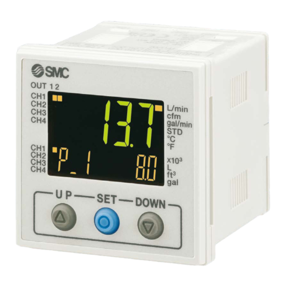
3-Screen Display
4-Channel Flow Monitor
4
Up to
can be connected!
Digital Flow Switch for Air
PF2A
PFG200
flow sensors
It is possible to change the settings
while checking the measured value.
Main screen
Sub screen
¡Input Range Selection
Applicable Flow Sensor Variations
3-Color Display
Digital Flow Switch for Water
PF3W-Z
Series
Measured value (Current flow value)
Left side
Right side
Label (Display item), Set value (Threshold value)
3
p.
3-Color Display
Digital Flow Switch for Water
PF3W
Visualization of Settings
Set value
(Threshold value)
Hysteresis value
Peak value
Bottom value
Channel display
Digital Flow Switch for Deionized
Water and Chemical Liquids
PF2D
CAT.ES100-157A
Advertisement
Table of Contents

Subscribe to Our Youtube Channel
Related Manuals for SMC Networks PFG200 Series

Summary of Contents for SMC Networks PFG200 Series
- Page 1 3-Screen Display 4-Channel Flow Monitor Up to flow sensors can be connected! It is possible to change the settings Visualization of Settings while checking the measured value. Set value (Threshold value) Main screen Measured value (Current flow value) Hysteresis value Peak value Left side Right side...
- Page 2 PFG200 4-Channel Flow Monitor 3-Screen Display Series Visualization of Settings Item and set value are displayed together. Existing model PFG200 Easy to confirm the displayed item Switches between displays Mode Examples Set value Set value Set hysteresis Normal output (Threshold value) Reversed output (Threshold value) Hysteresis...
- Page 3 PFG200 4-Channel Flow Monitor 3-Screen Display Series Centralized Control Saves Installation Space. reduction in installation space (Compared with the panel mounted PFG20m) 40 mm PFG20m 138 mm Compared with the panel mounted PFG300 Accumulated Flow Measurement A single product can manage the accumulated flow in four lines.
- Page 4 PFG200 4-Channel Flow Monitor 3-Screen Display Series Input Range Selection (for Pressure/Flow rate) M For Digital Flow Switch for Air / PF2MC7 PF2MC7501 Display PF2MC7102 1000 PF2MC7202 2000 Set A and B to the values shown in the table on the left. Input voltage 1 V The sensor input range can be set to the required M For Flow Sensor / PFMV5...
- Page 5 PFG200 4-Channel Flow Monitor 3-Screen Display Series Hub Function Converts analog signals to digital signals Fieldbus and supports IO-Link A currently used sensor can be used. ∗ Supports analog voltage output 1-5 V ocess data IO-Link Master Field setting and confirmation of measured Analog voltage Analog voltage...
- Page 6 PFG200 4-Channel Flow Monitor 3-Screen Display Series IO-Link is an open communication interface technology between the sensor/ actuator and the I/O terminal that is an international standard, IEC61131-9. Visualization of operation/equipment status Remote monitoring and control by communication Configuration File (IODD File ∗ ...
- Page 7 PFG200 4-Channel Flow Monitor 3-Screen Display Series Series Variations Digital Sensor Monitor PSE200A PFG300 PFG200 Catalog PDF Repeatability ±0.1 % (F.S.) ±0.1 % (F.S.) Voltage 12 to 24 VDC 12 to 24 VDC No. of outputs for switch 2 outputs 5 outputs Analog output —...
- Page 8 C O N T E N T S PFG200 4-Channel Flow Monitor 3-Screen Display Series How to Order p. 8 ·········································································································································· Specifications p. 9 ······································································································································· Applicable Flow Sensors p. 11 ············································································································ Internal Circuits and Wiring Examples p. 11 ·············································································· Dimensions p.
- Page 9 3-Screen Display 4-Channel Flow Monitor PFG200 Series How to Order PFG20 0 M Input/Output specification Symbol Description NPN 5 outputs + External input PNP 5 outputs + External input 2 ∗ IO-Link + NPN 4 outputs or NPN 5 outputs (SIO mode) Option 3 3 ∗...
-
Page 10: Pf2(3)W504
PFG200 Series For flow switch precautions and specific product precautions, refer to the “Operation Manual” on the SMC website. Specifications PFG20m Series Series PF2A510 PF2A550 PF2A511 PF2A521 PF2A551 PF2(3)W504 PF2(3)W520 Applicable SMC flow sensor Rated flow range 1 to 10 L/min 5 to 50 L/min 10 to 100 L/min 20 to 200 L/min 50 to 500 L/min 0.5 to 4 L/min 2 to 16 L/min... -
Page 11: Pf2(3)W540
PFG200 Series 3-Screen Display 4-Channel Flow Monitor For flow switch precautions and specific product precautions, refer to the “Operation Manual” on the SMC website. PFG20m Series Series PF2(3)W540 PF2(3)W511 PF3W521 PF2D504 PF2D520 PF2D540 Applicable SMC flow sensor Rated flow range 5 to 40 L/min 10 to 100 L/min 50 to 250 L/min... -
Page 12: Table Of Contents
PFG200 Series Applicable Flow Sensors Rated flow range [L/min] Applicable SMC flow sensor 0.4 0.5 1 2 PF2A510 PF2A550 PF2A511 PF2A521 PF2A551 PF2(3)W504 PF2(3)W520 PF2(3)W540 PF2(3)W511 PF3W521 PF2D504 PF2D520 PF2D540 Internal Circuits and Wiring Examples PFG20 Input/Output specifications Brown DC(+) Analog voltage input DC(−) Yellow External input... -
Page 13: Gray Ch2_Out1
PFG200 Series 3-Screen Display 4-Channel Flow Monitor Internal Circuits and Wiring Examples PFG20 Input/Output specifications · IO-Link/NPN open collector 1 output + NPN open collector 4 outputs When used as an IO-Link device Brown L + Analog voltage input DC(−) Yellow N.C. -
Page 14: Gray Ch2_Out1
PFG200 Series Internal Circuits and Wiring Examples PFG20 Input/Output specifications · IO-Link/PNP open collector 1 output + PNP open collector 4 outputs When used as an IO-Link device Brown L + Analog voltage input DC(−) Yellow N.C. DC(+) Analog voltage input Black C/Q DC(−) White CH1_OUT2... - Page 15 PFG200 Series 3-Screen Display 4-Channel Flow Monitor Internal Circuits and Wiring Examples PF3W5m-1T When using the (with temperature sensor) and measuring instantaneous flow and temperature simultaneously Example) PF3W520-03-1T (2 units) + PFG200-M (for 4 analog outputs with 2 units) Brown DC(+) Black Flow rate analog output Blue...
- Page 16 PFG200 Series Dimensions Sensor connector 40.1 (7.5) (Option) Sensor connector (4P x 4) Connector (Option) Pin no. Terminal DC (+) DC (–) IN (1 to 5 V) Power supply/Output connector (8P) Power supply/Output connection cable (Accessory) Pin no. 8 Yellow 7 Green 6 Red 5 Gray...
- Page 17 PFG200 Series Function Details Display examples of the main and sub (set value) screens of each mode. (When 100 L/min range is selected) Hysteresis mode, Normal output Threshold value setting Hysteresis setting Switch ON Switch ON Turns ON at the Difference between set value or more.
- Page 18 PFG200 Series Function Details Peak/Bottom value indication function This function constantly detects and updates the maximum (minimum) flow when the power is supplied, and allows to hold the maximum (minimum) flow value. When the buttons are simultaneously pressed for 1 second or longer, while “holding”, the held value will be reset. Key-lock function This function prevents operation errors such as accidentally changing setting values.
- Page 19 PFG200 Series Function Details Function Details Snap shot function The current flow rate value can be stored to the switch output ON/OFF set point. When the items on the Sub display (left) are selected in either 3 step setting mode, Simple setting mode or Setting of each function mode, by pressing the buttons simultaneously for 1 second or longer, the value of the sub display (right) will show "----", and the values corresponding to the current flow rate are automatically displayed.
- Page 20 These safety instructions are intended to prevent hazardous situations and/or Safety Instructions equipment damage. These instructions indicate the level of potential hazard with the labels of “Caution,” “Warning” or “Danger.” They are all important notes for ∗1) safety and must be followed in addition to International Standards (ISO/IEC) and other safety regulations.
Need help?
Do you have a question about the PFG200 Series and is the answer not in the manual?
Questions and answers