Advertisement
Quick Links
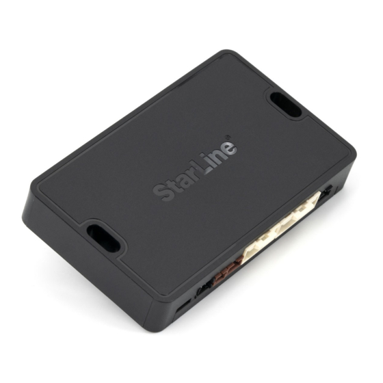
S9
Bluetooth transceiver
Mounting recommendations
Mount the main unit at a distance not less 10 cm from the
metal surfaces, to avoid Bluetooth and RF 868 MHz signal
transmission interference.
X7
Microphone (option)
X1
X2
RF 868 MHz transceiver
module with service button
X3
X4
X5
X6
GPS+GLONASS
USB-connector
GSM transceiver
For convenient setup, diagnostics and software upgrade use the free StarLine Master
software available at
help.starline.ru/slm
Login into the program with a service code in the owner's plastic card.
The manufacturer StarLine ScPA LLC reserves the right to make technical
improvements not shown in this diagram.
Information on firmware updates, actual versions of operation and installation
manuals are available at help.starline.ru.
General installation speci cations
The security system is designed for installation on vehicles with 12V on board voltage.
Prior to installation, make sure that the vehicle equipment circuits, to which the system is connected, are in suitable operating condition and no any trouble codes and check engine are indicated.
The system installation should be carried out according to the connection diagram.
The "ground" wire of the main unit should be connected first to a car body ground with an original screw.
Mount the wiring far from sources of electrical interference: ignition coils, high-voltage wires, etc.
Make sure that the harness is not lay in contact with the moving parts of the vehicle: pedals, steering shaft etc.
Connect all the harness to the main unit sockets only after all wires mounting is complete.
Do no fit the engine temperature sensor near the exhaust manifold, otherwise it may cause sensor overheating and damage.
Only the qualified and trained fitter may carry out the security system installation.
The configured parameters of the security systems must comply with a vehicle manual instruction requirements.
Security – telematic
V 2
system connection diagram
X1
X3 channel automatically detects the type of connected device
(external transceiver or service button). Auto detection is active
Temperature sensor
when the channel function is "Not set" in configuration.
transceiver
Check other available
connection options at
help.starline.ru
X2
red
Unit power supply
black
black-white
Security status output (200 мА) (–)
yellow-white
Door open simulation output (200 mA) (–)
black-red
Engine blocking output (200 mA) (–)
green-yellow
Comfort closure output (200 mA) (–)
gray-black
Engine run control input
yellow
Ignition input (+)
pink
Bypass module control output (200 mA) (–)
blue-red
Parking brake input (–)
purple
R4 code relay control output (200 mA) (–)
orange-white
Trunk trigger input (–)
gray
Siren control output (2 A) (+)
orange-violet
Brake pedal input (+)
yellow-black
Trunk unlock output (200 mA) (–)
blue-black
Door trigger input (+/–)
yellow-red
Door two-step unlock output (200 mA) (–)
orange-gray
Hood trigger input (–)
blue
+12 В
green
orange-white
CAN-H B
gray-white
LIN A
orange
CAN-L B
white
LIN B
brown
CAN-L A
white-blue
LIN C
brown-white
CAN-H A
white-green
LIN D
white-black
StarLine data bus
orange-black
DVR control output (2А) (+)
blue
ACC / Starter protection output (200 mA) (–)
black-yellow
Starter output (200 mA) (–)
yellow
IGN 1 output (200 mA) (–)
orange
Starter protection/ ACC output (200 mA) (–)
green
IGN 2 output (200 mA) (–)
red
+12V output (500 mA) (+)
For the cars equipped with CAN/LIN bus make a connection via the embedded digital CAN/LIN
interface, for the elder cars make an analogue connection.
Find information and wiring tips on vehicles and features supported with CAN/LIN connection at
can.starline.ru
Storage battery
3 А
10 А
To the yellow
(–)
wire of
85
connector X1
30
87а
87
86
(+)
Ignition lock
command
«Open»
(–)
command
85
«Close»
30
87а
87
Connect actuators
86
in parallel
(+)
Set X2:6 blue wire as Starter protection and X2:15 orange wire as Engine
start: ACC in StarLine Master configuration program.
+ 12 V
30 А
To the yellow
wire of connector X1
Blocking relay
(–)
in the set
85
30
Common
87
NC
86
(+)
NO
Ignition 1
Autostart connection diagrams
Power module V1
To connector Х2
30 А
+ 12 V
Ignition 2
Ignition 1
Accessories
Starter
+12 V
Power module V2
Ignition 2
Ignition 1
Accessories
Starter
+12 V
Ignition lock
To connector Х2
Advertisement

Related Manuals for Starline S9


Summary of Contents for Starline S9
- Page 1 GSM transceiver help.starline.ru 87а Starter Connect actuators +12 V in parallel For convenient setup, diagnostics and software upgrade use the free StarLine Master orange-white CAN-H B software available at help.starline.ru/slm gray-white LIN A Set X2:6 blue wire as Starter protection and X2:15 orange wire as Engine Login into the program with a service code in the owner’s plastic card.
- Page 2 The owner authorization code consists of a code sequence containing from 3 to 30 OEM buttons pressing. The list of supported OEM buttons is available at can.starline.ru. If a service button LED ash does not follow after pressing of OEM button, so this pink button is not supported for this car.
Need help?
Do you have a question about the S9 and is the answer not in the manual?
Questions and answers