
Related Manuals for Buck 1011C


Summary of Contents for Buck 1011C
- Page 1 MODEL 1011C HYGROMETER OPERATING MANUAL December 2008 BUCK RESEARCH INSTRUMENTS, LLC PO Box 19498 Boulder, CO 80308 Copyright 2008. Buck Research Instruments, LLC All rights reserved.
-
Page 2: Table Of Contents
- 2 - TABLE OF CONTENTS 1.0 INTRODUCTION 1.1 General Operational Description 1.2 Brief Physical Description 1.3 Specifications 1.4 List of improvements from the 1011B 1.5 Acknowledgment 2.0 CONTROLS, CONNECTORS, AND MAJOR COMPONENTS p.11 2.1 Sensing Unit 2.2 Control/Indicator Unit 2.3 Power Unit 2.4 Cables 2.5 Optional Accessories... - Page 3 - 3 - FIGURES Number Title Model 1011C Dew Point Hygrometer System Depression capability Dew Point Sensing Unit p.12 Control/Indicator Unit p.14 Power Unit, External p.15 Power Unit, Internal p.17 Sensing Unit: Mounting and Assembly p.20 Sensing Unit, Internal p.22 Flow Test Fixture Hookup p.23...
- Page 4 - 4 - LIST OF TABLES Number Title 1011C Connectors p.39 Dew Point to Frost Point Conversions p.40 Dew Point Error Due to Pressure Change in Sampling System p.41 APPENDIXES 1011C Pin Out p.30 Humidity Conversion Equations p.42 Warranty p.44...
-
Page 5: Introduction
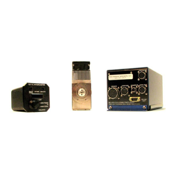
The signal output is a voltage corresponding to the temperature of the mirror. The 1011C consists of three distinct units – a Sensor unit, a Power unit and a Control/Indicator unit. The Sensor unit contains a three-stage thermoelectric cooler (TEC) capable of reaching frost points normally encountered at altitudes up to 45,000 feet. -
Page 6: Brief Physical Description
The Maintenance kit: Consisting of bottles for water and acetone, cotton swabs and spare gaskets and o-rings. Unlike the 1011B, the 1011C does not come with a calibration plug. This is because the 1011C uses an ultra-stable thermistor instead of an RTD, which improves speed of response and is far less susceptible to drift. - Page 7 - 7 - Figure 1. Dew Point Hygrometer System (shown with optional cables)
-
Page 8: Specifications
- 8 - 1.3 SPECIFICATIONS -75 to +50 °C nominal Dew point range: (see also Figure 2) Accuracy ± 0.1° C RS-232 ± 0.3° C LED display Response time: Variable (see Sect. 4.2.1) Outputs Analog: Dew point: 0.08 v/°C, 6v = 0°C Control voltage: 0 –... - Page 9 - 9 -...
-
Page 10: Acknowledgment
- 10 - 1.4 NOTE TO USERS OF 1011B SYSTEMS The following is a list of improvements made: 1. 28 VDC operation. 2. RS-232 data output 3. Improved accuracy, ± 0.1 degree C over entire range* 4. Improved servo control, reducing oscillations be a factor of 10. 5. -
Page 11: Controls, Connectors, And Major Components
B. Mounting collar. The mounting collar has 6 holes drilled in it that are ready to be tapped for either 8-32 or M4 screws for mounting. Buck Research Instruments, LLC does not tap these holes unless specifically requested by the customer, as mounting configurations and requirements vary from aircraft to aircraft. - Page 12 - 12 - Figure 3. Dew Point Sensing Unit...
-
Page 13: Control/Indicator Unit
- 13 - CONTROL/INDICATOR UNIT (Figure 4) Function switch (S1) - applies power to the various system supplies, and provides the following functions: OFF - no power applied to any circuit. DEW POINT - normal operating position. Allows system to maintain an equilibrium condensation layer on the mirror. - Page 14 - 14 - Figure 4. Control/Indicator Unit...
-
Page 15: Power Unit
- 15 - POWER UNIT (Figure 5) A. SENSOR Connector (J5) - for cable to sensor. B. CONT/IND Connector (J7) - for cable to Control/Indicator. C. DATA OUT Connector (J4) - provides analog signal outputs. D. POWER IN Connector (J1) - for connecting +28 VDC. E. -
Page 16: Cables
OPTIONAL ACCESSORIES Aspirating Kit. Provides airflow through the 1011C sensor when it is not exposed to in-flight conditions. It consists of an aspirating fixture which attaches to the sensor, a pump, a floating ball flowmeter with control valve, and a length of non- hygroscopic tubing with fittings. - Page 17 - 17 - Figure 6. Power Unit, Internal...
-
Page 18: Installation
- 18 - SECTION 3. INSTALLATION UNPACKING PROCEDURE Remove system components from shipping containers and situate near a 28 VDC power source. If possible, save shipping containers for future use. Make sure that all system components are accounted for (Figure 1). Ascertain they are properly matched by serial number, or have been calibrated together. - Page 19 - 19 - The sensor should be mounted as shown in Figure 7. Initially, orient the sensor so the inlet fitting points downstream, parallel to the airstream, with the inlet and exhaust holes pointed downwards. As soon as practical, adjust for proper flow and pressure change in the cavity, according to Section 3.5.
- Page 20 - 20 - Figure 7. Sensing Unit: Mounting Note: #6-32 screws go into the mount collar, which has a maximum depth of 0.375”. Add this length to the total thickness of the aircraft skin and any plates used to deternine screw length.
-
Page 21: Leak Check
3.6 CABLING When cables are supplied with the 1011C and it is desired to use cables of different length than the 3 foot (1m) lengths originally supplied, factory-made cables of different lengths are available from Buck Research Instruments, LLC, on a special-order basis only. - Page 22 - 22 - any questions or doubts about making your own cable, please contact Buck Research Instruments, LLC and we would be happy to assist you. Figure 8. Sensing Unit, Internal...
- Page 23 - 23 - Figure 9. Flow Test Fixture Hookup...
-
Page 24: Operating Instructions
- 24 - SECTION 4. OPERATING INSTRUCTIONS 4.1 INITIAL SETUP 1. Ascertain that function switch S-1 is in OFF position. 2. Connect power unit, sensing unit, and control unit to their appropriate cables, and to 28 VDC (see Figure 13). Also, connect analog or digital recording devices as desired. -
Page 25: Supercooled Dew Points
- 25 - Since proper operation of a condensation hygrometer depends strongly on the condition of the mirror surface, the following discussion of the effects of various types of contaminants may be helpful. Particulate Contaminants. Particulate matter which is insoluble in water may accumulate on the mirror surface, but usually will not affect the instrument accuracy until the mirror reflectance is reduced substantially, and in many cases, will improve instrument response by providing condensation sites. -
Page 26: Low Frost Points
4.2.5 Pressure Effects The 1011C system will display the Dew/Frost Point at the pressure that the sensor chamber is exposed to. The location of the sensor probe on the aircraft can influence the pressure. Attaching an altimeter and comparing it with the aircraft altimeter is a convenient way of accomplishing this. -
Page 27: Operation While Parked Or Off The Aircraft
- 27 - Under conditions of abrupt transition from dry to moist conditions, particularly when accompanied by a transition from cold to warm temperatures, the mirror may accumulate an overload of moisture. It may then take several minutes for the sensor to “dry out”. The process can be speeded by temporarily setting the function switch of the control/indicator unit to the BALance position, thereby heating the mirror. - Page 28 - 28 - FIGURE 10. System Response Characteristics...
-
Page 29: Preventive Maintenance And Troubleshooting
- 29 - SECTION 5. PREVENTIVE MAINTENANCE AND TROUBLESHOOTING A periodic inspection and preventive maintenance program will significantly improve the performance and longevity of this equipment. The main items of routine maintenance are: periodic inspection,and mirror cleaning. Maintenance of the system is otherwise limited to that associated with troubleshooting the system. - Page 30 K-Ground – (do not use with 4-20 mA sensor) When using a 0-5 or 1-5 VDC sensor, you must use D,E,J and K or the sensor will not work. Calibration instructions are available by request from Buck Research Instruments, LLC.
- Page 31 - 31 - Recommended cable: Belden YQ27540 Figure 11. Wiring Diagrams...
- Page 32 - 32 - Recommended cable: Belden YQ27540 Wiring Diagrams Continued...
- Page 33 - 33 -...
- Page 34 - 34 - Figure 13. Vapor Pressure e vs. Dew Point T Saturation Vapor Pressure e vs. Temperature T...
- Page 35 - 35 - Figure 13. Vapor Pressure e vs. Dew Point T Saturation Vapor Pressure e vs. Temperature T Figure 14. Absolute Humidity vs. Dew Point...
- Page 36 - 36 - Figure 15.
- Page 37 - 37 - Figure 16. Aspirating Fixture Hookup...
- Page 38 - 38 - Figure 17. 1011C Hygrometer Complete...
- Page 39 - 39 - Table 1. 1011C Connectors Power Unit Power In PTO2E8 – 3P Data Out PTO2E12 – 10S Sensor PTO2E20 – 16S Control Indicator PTO2E14 – 18S Serial Out 9 pin D-sub Control Indicator PTO2E14 – 18P Cables Sensor PTO6E20 –...
- Page 40 - 40 - Table 2. Dew Point to Frost Point Conversions...
- Page 41 - 41 - Table 3. Dew Point Error due to Pressure Change in Sampling System...
- Page 42 (Revised 7/96) Computer-efficient algorithms for converting among several humidity units, as used in HCON, are given here. They utilize vapor pressure formulations developed by A. Buck (1981). = dew or frost point in deg C = vapor pressure in millibars...
- Page 43 - 43 - NOTE 1: f1(DP) and f2(e) are variations on vapor pressure formulations found in Buck, A: J Appl Met 20, pp 1527-1532 (1981). They are given by: e vs. DP or es vs. T: f1(DP) = EF x aw x exp [(bw - DP/dw) x DP/(DP + cw)] (over water) = EF x ai x exp [(bi - DP/di) x DP/(DP + ci)] (over ice) DP vs.
- Page 44 - 44 - APPENDIX 3. WARRANTY Manufacturer warrants that the items delivered shall be free from defects (latent and patent) in material and workmanship for a period of one year after acceptance of the specific goods by Buyer, or within 30 days of receipt of the item, whichever comes first. The Buyer’s sole and exclusive remedy under this warranty shall be limited to repair or replacement.
- Page 45 - 45 - RS-232 Data Stream and Pin Out for 1011C Aircraft Hygrometer Pin Out: 2 – Rx (Data In) 3 – Tx (Data Out) 5 – Ground 9600 baud, 8-N-1 parity. Use included null modem cable to connect to computer running Hyperterminal or similar serial port emulator software.
- Page 46 Data Out Conntector Pins: A-DPI Dew point indication – binary output of 0 V or 5 V. If 1011C is balanced and controlling, output is 5 V, else output is 0 V. Note: this is listed as RTD in the manual.
- Page 47 - 47 -...
- Page 48 - 48 -...
Need help?
Do you have a question about the 1011C and is the answer not in the manual?
Questions and answers