Table of Contents
Advertisement
Quick Links
User Manual
Closed-Loop Stepper System
AiC-EC Series
MMD-AiC-ECU1-V1.1-2107US
Thank you for purchasing Autonics product.
This manual contains information about the product and its proper use,
and should be kept in a place where it will be easy to use.
www.autonics.com
Advertisement
Table of Contents

Related Manuals for Autonics AiC-EC Series


Summary of Contents for Autonics AiC-EC Series
- Page 1 User Manual Closed-Loop Stepper System AiC-EC Series MMD-AiC-ECU1-V1.1-2107US Thank you for purchasing Autonics product. This manual contains information about the product and its proper use, and should be kept in a place where it will be easy to use. www.autonics.com...
- Page 3 Preface Preface Thank you for purchasing Autonics product. Please familiarize yourself with the information contained in the Safety Considerations sections before using this product. This manual contains information about the product and its proper use, and should be kept in a place where it will be easy to access.
- Page 4 • This manual may not be edited or reproduced in either part or whole without permission. • This manual is not provided as part of the product package. Visit our website (www.autonics.com) to download a copy. • The manual’s content may vary depending on changes to the product’s software and other unforeseen developments within Autonics, and is subject to change without prior notice.
- Page 5 Supplementary information for a particular feature. Failure to follow instructions can result in serious injury or death. Failure to follow instructions can lead to a minor injury or product damage. An example of the concerned feature’s use. Annotation mark. © Copyright Reserved Autonics Co., Ltd.
- Page 6 Failure to follow this instruction may result in burn due to high temperature of the surface. 11. Upon occurrence of an error, disconnect the power source. Failure to follow this instruction may result in personal injury, fire or electronic shock. © Copyright Reserved Autonics Co., Ltd.
- Page 7 Failure to follow this instruction may result in product damage or degradation by heat. 04. Keep the product away from metal chip, dust, and wire residue which flow into the unit. Failure to follow this instruction may result in fire or product damage. © Copyright Reserved Autonics Co., Ltd.
- Page 8 Failure to follow this instruction may result in burn or electric shock due to high temperature of the surface. 09. Emergency stop directly when error occurs. Failure to follow this instruction may result in personal injury or fire. © Copyright Reserved Autonics Co., Ltd.
- Page 9 The above specifications, dimensions, etc. are subject to change and some models may be discon- tinued without notice. Be sure to follow cautions written in the instruction manual, user manual, and technical descrip- tions (catalog, website). © Copyright Reserved Autonics Co., Ltd.
- Page 10 • This unit may be used in the following environments. - Indoors (in the environment condition rated in ‘Specifications’) - Altitude max. 2,000 m - Pollution degree 2 - Installation category II © Copyright Reserved Autonics Co., Ltd.
- Page 11 - Indoors (in the environment condition rated in ‘Specifications’) - Altitude max. 2,000 m - Pollution degree 2 - Installation category II EtherCAT® is registered trademark and patented technology, licensed by Beckhoff Automation GmbH, Germany. © Copyright Reserved Autonics Co., Ltd.
- Page 12 Installation Direction of Motor ........................33 Panel Cut-out Dimensions ..........................34 Cautions during Connection with Load ..................... 35 Installation Conditions ..........................36 Connection ....................37 Standard Type..............................37 Built-in Brake Type ............................38 Motor Characteristic ..................39 © Copyright Reserved Autonics Co., Ltd.
- Page 13 10.3.1 Operation & I/O Active Level Setting ..................... 53 10.3.2 Home Search Mode ........................... 54 10.3.3 Parameter ..............................54 EtherCAT Communication ................55 11.1 EtherCAT Communication Overview ......................55 11.1.1 EtherCAT Communication Interface ....................... 55 © Copyright Reserved Autonics Co., Ltd.
- Page 14 12.4.1 Driving Method ............................84 12.4.2 Related Object ............................85 12.4.3 Operation Timing Chart..........................87 12.4.3.1 Normal Operation ..............................87 12.4.3.2 HALT Operation................................87 12.4.3.3 Internal Limit Operation ............................88 12.4.3.4 Quick Stop Operation ..............................88 © Copyright Reserved Autonics Co., Ltd.
- Page 15 14.1.1 Device type: [1000h] ..........................112 14.1.2 Error Register: [1001h] ..........................112 14.1.3 Device Name: [1008h] ..........................112 14.1.4 Hardware Version: [1009h] ........................112 14.1.5 Software Version: [100Ah] ........................112 14.1.6 Identity: [1018h] ............................113 © Copyright Reserved Autonics Co., Ltd.
-
Page 16: Statusword: [6041H]
14.5.9 Modes of Operation: [6060h] ......................... 136 14.5.10 Modes of Operation Display: [6061h] ....................136 14.5.11 Position Demand Value: [6062h] ......................136 14.5.12 Position Actual Value: [6064h] ....................... 136 14.5.13 Following Error Window: [6065h] ......................136 © Copyright Reserved Autonics Co., Ltd. - Page 17 14.5.40 Following Error Actual Value: [60F4h] ....................143 14.5.41 Digital Input: [60FDh] ..........................143 14.5.42 Digital Output: [60FEh] ........................... 144 14.5.43 Target Velocity: [60FFh] .......................... 144 14.5.44 Supported Drive Modes: [6502h] ......................145 Troubleshooting ..................146 © Copyright Reserved Autonics Co., Ltd.
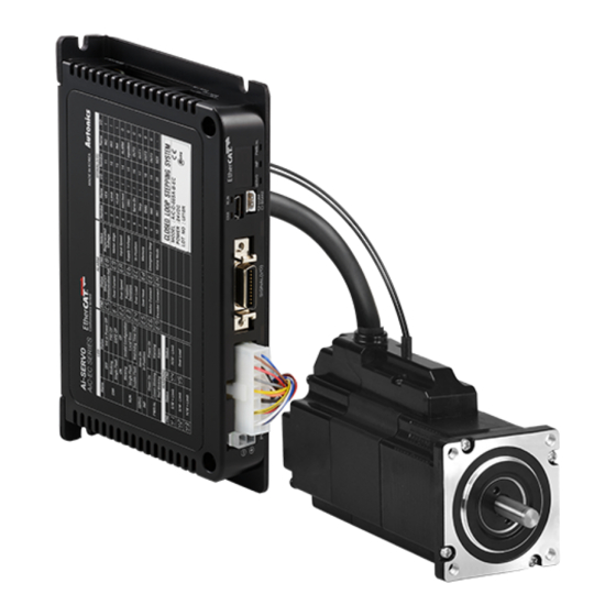
- Page 18 1 Product Overview Product Overview Features AiC-EC series is Ai-Servo with EtherCAT communication. This product supports stable compatibility with various master / slave with open protocol communication EtherCAT and is advantageous for control simultaneous multi-axis synchronized control through 100 Mbps baud rate.
- Page 19 Motor Motor Instruction manual Make sure all of the above components are included with your product package before use. If a component is missing or damaged, please contact Autonics or the product distributor. 1.2.2 Configuration Diagram EtherCAT comm. cable Ai-M Series...
- Page 20 □ 42 / 56 / 60 mm 4,000 PPR 10,000 PPR ⑥ Encoder resolution (1,000 PPR × 4) (2,500 PPR × 4) 16,000 PPR (4,000 PPR × 4) ⑦ Brake Built-in brake type ⑧ Comm. method EtherCAT communication © Copyright Reserved Autonics Co., Ltd.
- Page 21 □ 42 / 56 / 60 mm 4,000 PPR 10,000 PPR ⑤ Encoder resolution - (1,000 PPR × 4) (2,500 PPR × 4) 16,000 PPR (4,000 PPR × 4) No mark Standard type ⑥ Motor type Built-in brake type © Copyright Reserved Autonics Co., Ltd.
- Page 22 Please purchase the motor and driver separately. Refer to each insturction manula for more details. • Built-in Geared Motor frame Driver Motor Ai-M-42MA-G5 □ 42 mm AiC-D-42MA-EC Ai-M-42MA-G7.2 Ai-M-42MA-G10 Ai-M-60MA-G5 □ 60 mm AiC-D-60MA-EC Ai-M-60MA-G7.2 Ai-M-60MA-G10 © Copyright Reserved Autonics Co., Ltd.
- Page 23 1 Product Overview • Built-in Rotary Actuator Motor frame Driver Motor Ai-M-60MA-R5 □ 60 mm AiC-D-60MA-EC Ai-M-60MA-R7.2 Ai-M-60MA-R10 • © Copyright Reserved Autonics Co., Ltd.
- Page 24 Homing without an index pulse (Home sensor ON) Home search Homing on the index pulse Set the origin with home offset Set the origin and reset current position Torque homing search with home offset © Copyright Reserved Autonics Co., Ltd.
- Page 25 10 / 100 Mbps Max. ID settings Topology Star, Line, Tree 01) EtherCAT® is registered trademark and patented technology, licensed by Beckhoff Automation GmbH, Germany. 02) Max. connectable ID from Master is 1 to 65,535. © Copyright Reserved Autonics Co., Ltd.
- Page 26 ≈ 0.34 kg (≈ 0.45 kg) ≈ 0.41 kg (≈ 0.52 kg) ≈ 0.48 kg (≈ 0.59 kg) ≈ 0.67 kg (≈ 0.77 kg) ≈ 0.73 kg (≈ 0.83 kg) ≈ 0.80 kg (≈ 0.90 kg) © Copyright Reserved Autonics Co., Ltd.
- Page 27 Shaft perpendicularity 0.075 mm T.I.R. 01) Amount of radial shaft displacement when applying radial load to the end of the shaft. 02) Amount of axial shaft displacement when applying axial load to the motor shaft. © Copyright Reserved Autonics Co., Ltd.
- Page 28 ≤ 30 ms Releasing time ≤ 10 ms ≤ 20 ms 01) In order to reduce the heat generation of the built-in brake, the voltage drops from 24 VDCᜡ to 11.5 VDCᜡ to control © Copyright Reserved Autonics Co., Ltd.
- Page 29 3 Dimensions Dimensions Driver (unit: mm) 87.5 Above images may differ from actual units. © Copyright Reserved Autonics Co., Ltd.
- Page 30 ±0. 2 Ø8.5, 0.4 m Axial length 46 mm 59 mm 65 mm (3) Ai-M-35□B □35 ±1 ±1.5 4-M3 DP4 □26 ±0.2 ±0.2 Ø8.5, 0.4 m Axial length 41.5 mm 52 mm 68.5 mm © Copyright Reserved Autonics Co., Ltd.
- Page 31 Ø9.8, 0.25 m Axial length 43.4 mm 56.4 mm 77.4 mm (6) Ai-M-60□A □60 20.6 A+33.8 ±1 ±1.5 4-Ø5 + 0.3 □50 ±0.25 ±1.1 ±0.2 Ø9.8, 0.25 m Axial length 48 mm 68.9 mm 85.9 mm © Copyright Reserved Autonics Co., Ltd.
- Page 32 43.4 mm 56.4 mm 77.4 mm (3) Ai-M-60□A-B □60 20.6 A+68.8 ±1 ±2 4-Ø5 + 0.3 □50 ±0.25 ±1.1 ±0.2 Ø1.5×2-wire 0.23 m Ø10, 0.18 m Axial length 48 mm 68.9 mm 85.9 mm © Copyright Reserved Autonics Co., Ltd.
- Page 33 D = 0 D = 5 D = 10 D = 15 □ 20 mm □ 28 mm □ 35 mm Under load of motor □ 42 mm □ 56 mm / □ 60 mm © Copyright Reserved Autonics Co., Ltd.
- Page 34 When mounting motors, use hexagon socket screws, spring washers and flat washers. Do not draw the wire with over strength 30N after wiring the encoder. © Copyright Reserved Autonics Co., Ltd.
- Page 35 (3) Load Connection with Gear The motor shaft and the load shaft should be parallel. Connect the motor shaft to the center of gear teeth side to be interlocked. © Copyright Reserved Autonics Co., Ltd.
- Page 36 The place with less salt content • The place with less electronic noise occurs by welding machine, motor, etc. • The place where radioactive substances and magnetic fields does not exist and is not in the vacuum status © Copyright Reserved Autonics Co., Ltd.
- Page 37 Hold Off Stop 4.7 kΩ +5 VDCᜡ IN1 to IN5 In-Position F.G. Alarm N·C OUT1 to OUT4 ECAT IN / ECAT OUT POWER Index 24 VDCᜡ Input Output 4, 5, N·C 7, 8 N·C © Copyright Reserved Autonics Co., Ltd.
- Page 38 Hold Off Stop 4.7 kΩ +5 VDCᜡ IN1 to IN5 In-Position F.G. Alarm N·C OUT1 to OUT4 ECAT IN / ECAT OUT POWER Index 24 VDCᜡ Input Output 4, 5, N·C 7, 8 N·C © Copyright Reserved Autonics Co., Ltd.
- Page 39 1500 2000 2500 3000 Speed [rpm] (2) Ai-M-28□B 0.20 Ai-M-28LA-□ 0.15 Ai-M-28MA-□ 0.10 Ai-M-28SA-□ 0.05 1000 1500 2000 2500 3000 Speed [rpm] (3) Ai-M-35□B Ai-M-35LA-□ Ai-M-35MA-□ Ai-M-35SA-□ 1000 1500 2000 2500 3000 Speed [rpm] © Copyright Reserved Autonics Co., Ltd.
- Page 40 Ai-M-42LA-□ Ai-M-42MA-□ Ai-M-42SA-□ 1000 1500 2000 2500 3000 Speed [rpm] (5) Ai-M-56□A-□ Ai-M-56LA-□ Ai-M-56MA-□ Ai-M-56SA-□ 1000 1500 2000 2500 3000 Speed [rpm] (6) Ai-M-60□A-□ Ai-M-60LA-□ Ai-M-60MA-□ Ai-M-60SA-□ 1000 1500 2000 2500 3000 Speed [rpm] © Copyright Reserved Autonics Co., Ltd.
- Page 41 Connects the motor and the encoder to the driver. Function Function +5 VDCᜡ Encoder A Encoder A 13 12 11 10 9 Encoder B Encoder B Encoder Z Encoder Z N·C MOTOR Motor A Motor B Motor A Motor B © Copyright Reserved Autonics Co., Ltd.
- Page 42 Function 24VDCᜡ BRAKE The corresponding connector is only available in built-in brake type. 7.1.7 EtherCAT Comm. Connector (ECAT IN / ECAT OUT) Function Function N·C 8···1 8···1 N·C ECAT IN ECAT OUT N·C N·C © Copyright Reserved Autonics Co., Ltd.
- Page 43 Turns ON depending on communication fail status (ERR) (RUN / ERR) EtherCAT comm. indicator Green Turns ON or flashes depending on connection status For more information of EtherCAT comm. indicator, refer to ‘11.1.2 Operation Indicator’ . © Copyright Reserved Autonics Co., Ltd.
- Page 44 Red-5 Recommended to use ferrite core at both ends of the cable. The model name is 010, 020, 030, 050, 070, 100, 150, 200 which indicates the cable length. E.g.) CO20-MP070-R: 7m I/O cable © Copyright Reserved Autonics Co., Ltd.
- Page 45 : It recognizes as Servo ON signal, the motor phase current is applied and torque is returned. Servo ON/OFF indicator, In-Postion and its indicator turns ON. Make sure to use this while the motor is stopped. It may cause safety risk while the motor is driving. © Copyright Reserved Autonics Co., Ltd.
- Page 46 In case of using external power over 24 VDCᜡ, select R that I (forward current of primary LED) of phothocoupler to be around 2.5 mA (max. 10 mA). VEX - 1.25 V - 10 × 10 Ω 0.0025 A © Copyright Reserved Autonics Co., Ltd.
- Page 47 Fast Response: when the deviation between target position and current position is less than setting value, outputs In-Position immediately. • Accurate Response: when the deviation between target position and current position is less than setting value and remains over 50 ms, outputs In-Position. © Copyright Reserved Autonics Co., Ltd.
- Page 48 External power input over 5-50 VDCᜡ is available with open collector method. Select R that I (collector current of secondary LED) of phothocoupler to be around 10 mA. VEX - 0.7 V Ω 0.01 A © Copyright Reserved Autonics Co., Ltd.
-
Page 49: Operation Enabled
24 VDCᜡ to the brake, and controls to remain the brake lock released after 0.2 sec. Driver Power Operation Enabled Brake Power 0.2 s Locked Unlocked Locked Make sure to ventilate or cool the brake so that the temperature remains below 100 ℃. © Copyright Reserved Autonics Co., Ltd. - Page 50 01) Visit Autonics website (www.autonics.com) to download newest version of ‘atMotion’ . 02) Run ‘atMotion’ installed on PC. 03) On the left side, select ① ‘Supported Device List’ - ② ‘AiC-EC Series’ . 04) Set communication method as ‘RS-232’ at New DAQ interface.
- Page 51 07) On the right side, select ‘RS-232’ and set the baud rate. 08) Click ‘Connect’ on the top of the screen to connect the device. 09) To make sure the connection is connected properly, check the device node on the right side of screen. © Copyright Reserved Autonics Co., Ltd.
- Page 52 If the object is saved when the power is applied, save the parameters and re-apply the power. Save object will be saved in a batch. For more information, refer to ‘atMotion user manual’ . © Copyright Reserved Autonics Co., Ltd.
- Page 53 200Eh Assign Output3 Digital Outputs_BitMask_Universal3 Digital Outputs_BitMask_Universal4 Assign Output4 Remote Assign Input1 Remote Assign Input2 Remote Assign Input3 Remote Assign Input4 200Fh Remote Assign Input5 Remote Assign Input6 Remote Assign Input7 Remote Assign Input8 © Copyright Reserved Autonics Co., Ltd.
- Page 54 Max Profile Velocity 6085h Quickstop Deceleration 6065h Following Error Window 6067h Position Window Software Position Limit- 607Dh Software Position Limit+ 2015h Reference Resolution 2005h Stop Current Set Control Gain 2003h P GAIN I GAIN © Copyright Reserved Autonics Co., Ltd.
- Page 55 SM2: Process Data input SM3: Process Data output Mailbox SDO Mapping Device profile IEC 61800-7 CiA402 Drive Profile Support protocol CAN application protocol over EtherCAT DC setting range 250us, 500us, 1ms, 2ms, 4ms, 8ms © Copyright Reserved Autonics Co., Ltd.
- Page 56 To change the ID setting value, re-apply the power. The available range of setting value is 0 to 99. Setting Comm. ID (×10) Comm. ID (×1) 0×10 1×10 2×10 3×10 4×10 5×10 ×10 ×1 6×10 7×10 8×10 9×10 © Copyright Reserved Autonics Co., Ltd.
- Page 57 CANopen CiA402 Driver profile Application Layer CANopen Object Dictionary Process Data Service Data Object (SDO) CoE / SoE Mailbox Process Data Data link layer (DL) FMMU0 FMMU1 EtherCAT Slave Controller EtherCAT Physical Layer Physical layer (PL) © Copyright Reserved Autonics Co., Ltd.
- Page 58 Through PDO comm., the command is able to received from Master to driver. Operational (OP) SDO (Mailbox comm.), TxPDO (transmit)and RxPDO (receive) are available. Following state is mainly used for firmware upgrade, and Bootstrap (Boot) SDO (Mailbox comm.) is only available. © Copyright Reserved Autonics Co., Ltd.
- Page 59 At first, the data is written to a buffer and saved in a buffer until the receive read the buffer. There is no data loss due to Handshake mechanism is used. It is asynchronous and is generally used for SDO communication. Master Mailbox Slave Read Empty Write Full Read Empty © Copyright Reserved Autonics Co., Ltd.
- Page 60 It is used for PDO communication that operates as a periodic signal. Master EtherCAT Next Slave Write Begin Read Begin Buffer exchange Buffer exchange Write End Read End Read Begin Write Begin Buffer exchange Buffer exchange Read End Write End © Copyright Reserved Autonics Co., Ltd.
- Page 61 1A00h (TxPDO map 0) · · · 1600h 0 RxPDO map 1 1601h 1 RxPDO map 2 · PDO Mapping Object · · 1A00h 0 TxPDO map 1 1A01h 1 TxPDO map 2 · · · © Copyright Reserved Autonics Co., Ltd.
- Page 62 11 EtherCAT Communication 11.2.4.1 PDO Mapping AiC-EC series uses fixed PDO mapping. PDO mapping content cannot be changed but can be read or written through SDO. RxPDO is assigned to 1600h, 1601h, 1602h, and TxPDO is assigned to 1A00h, 1A01h, 1A02h.
- Page 63 Digital Inputs [60FDh] 11.2.5 Service Data Object(SDO) All objects defined in Object Dictionary are communicated asynchronously in Mailbox communication. It is used when the user sets a value for a specific object or monitors the status. © Copyright Reserved Autonics Co., Ltd.
- Page 64 11 EtherCAT Communication 11.3 EtherCAT Communication Sync Mode AiC-EC series is able to select total 3 communication sync mode. • Free-Run mode Slave operates asynchronously by internal timer event independent of synchronization signal. • SM Event sync mode Whenever RxPDO receive is completed from Master, SM event occurs.
-
Page 65: Fault
11.4 Drive State Machine (DSM) AiC-EC series supports CiA402 profile and can be moved through Controlword [6040h]. Also, the current status can be checked through Statusword [6041h]. In the following diagram, the square indicates the status, and No. 2 to 10 and 15 indicate the status control command. - Page 66 Bit 3 Bit 2 Bit 1 Bit 0 Not ready to switch ON × Switch ON disabled × Ready to switch ON × Switched ON × Operation enabled × Fault reaction active × Fault × © Copyright Reserved Autonics Co., Ltd.
- Page 67 12 EtherCAT Operation Mode EtherCAT Operation Mode AiC-EC series is able to operate the following modes. Mode Descriptions Modes of Operation Invalid drive function 0 (Factory default) Operating at designated target position Operating at specified speed Operating to designated target position according to real-time value...
-
Page 68: Access Pdo Mapping Value (Default)
6064h 0h Position Actual Value INT32 RO TxPDO 60FDh 0h Digital Input TxPDO Detail 01) Statusword [6041h] Remote (Bit 9) returns ‘0’ while PDO or SDO command is in progress, returns ‘1’ after completed. © Copyright Reserved Autonics Co., Ltd. - Page 69 Quick Stop Deceleration[step/s 500 to 500,000,000 (5,000,000) Save After stop 60B8h 0h Touch Probe Function 0000h to FFFFh Immed. 60FEh 1h Output setting 0 to FFFF FFFFh (0) Immed. 60FDh 0h Digital Input Detail © Copyright Reserved Autonics Co., Ltd.
- Page 70 Controlword [6040h] New set Position (Bit 4) is valid only in rising edge. [6060h].1 PP mode [607Ah] 100000 150000 Target Position [6040h].4 Set Position [6040h].5 Set Position setting [6040h].6 ABS / INC [6040h].8 HALT [6041h].12 Position received [6064h] 100000 150000 Position Actual Value [6041h].10 Target Reached © Copyright Reserved Autonics Co., Ltd.
- Page 71 Set Position setting [6040h].6 ABS / INC [6041h].12 Position received HW: rapid stop / SW: deceleration stop at speed set in [2001h] [6064h] xxxx 50000 Position Actual Value [6041h].10 Target Reached [6041h].11 Internal Limit Active © Copyright Reserved Autonics Co., Ltd.
- Page 72 200000 Target Position [6040h].2 Quick Stop [6040h].4 Set Position [6040h].5 Set Position setting [6040h].6 ABS / INC [6041h].12 Position received Stop at speed set in [605Ah] [6064h] xxxx Position Actual Value [6041h].10 Target Reached © Copyright Reserved Autonics Co., Ltd.
- Page 73 04) Set the objects required for driving. (Refer to the following table for related object.).) 05) Enter command speed in Target Velocity [60FEh]. Controlword [6040h] Statusword [6041h] Slave Target Velocity [60FFh] Feedback Velocity [606Ch] Control Function Modes of Operation [6060h] Modes of Operation Display [6061h] © Copyright Reserved Autonics Co., Ltd.
- Page 74 606Ch 0h Velocity Actual Value INT32 RO TxPDO 60FDh 0h Digital Input TxPDO Detail 01) Statusword [6041h] Remote (Bit 9) returns ‘0’ while PDO or SDO command is in progress, returns ‘1’ after completed. © Copyright Reserved Autonics Co., Ltd.
- Page 75 Quick Stop Deceleration[step/s 500 to 500,000,000 (5,000,000) Save After stop 60B8h 0h Touch Probe Function 0000h to FFFFh Immed. 60FEh 1h Output setting 0 to FFFF FFFFh (0) Immed. 60FDh 0h Digital Input Detail © Copyright Reserved Autonics Co., Ltd.
- Page 76 Previous position value will be ignored after HALT stop. [6060h].3 PV mode [60FFh] 1500 Target Velocity [6040h].8 HALT HW: rapid stop / SW: deceleration stop at speed set in [2001h] [606Ch] 1500 1500 Velocity Actual Value [6041h].10 Target reached [6041h].12 Speed Zero © Copyright Reserved Autonics Co., Ltd.
- Page 77 Statusword [6041h] Speed Zero (Bit 12) will be SET after stop completed by Quick Stop. [6060h].3 PV mode [60FFh] 1500 Target Velocity [6040h].2 Quick Stop Stop at speed set in [605Ah] [606Ch] 1500 Velocity Actual Value [6041h].10 Target reached [6041h].12 Speed Zero © Copyright Reserved Autonics Co., Ltd.
- Page 78 05) Start operation with Target Position [607Ah] value transmitted from Master. Controlword [6040h] Statusword [6041h] Slave Target Position [607Ah] Position Actual Value [6064h] Control Function Modes of Operation [6060h] Modes of Operation Display [6061h] © Copyright Reserved Autonics Co., Ltd.
- Page 79 60BDh 0h INT32 RO TxPDO Down Edge Position 60FDh 0h Digital Input TxPDO Detail 01) Statusword [6041h] Remote (Bit 9) returns ‘0’ while PDO or SDO command is in progress, returns ‘1’ after completed. © Copyright Reserved Autonics Co., Ltd.
- Page 80 Quick Stop Deceleration[step/s 500 to 500,000,000 (5,000,000) Save After stop 60B8h 0h Touch Probe Function 0000h to FFFFh Immed. 60FEh 1h Output setting 0 to FFFF FFFFh (0) Immed. 60FDh 0h Digital Input Detail © Copyright Reserved Autonics Co., Ltd.
- Page 81 CSP mode [607Ah] 0 to 10000 Target Position [6040h].8 HALT [6064h] Stop at speed set in [605Dh] 0 to xxxx Position Actual Value [6041h].11 Internal Limit Active [6041h].12 Cancel position command Target Position Ignored © Copyright Reserved Autonics Co., Ltd.
- Page 82 0 to 10000 -xxxx Target Position [6040h].8 HALT HW: rapid stop / SW: deceleration stop at speed set in [2001h] [6064h] 0 to xxxx -xxxx Position Actual Value [6041h].11 Internal Limit Active [6041h].12 Target Position Ignored © Copyright Reserved Autonics Co., Ltd.
- Page 83 If Controlword [6040h] Quick Stop (Bit 2) is RESET, the target position command will be invalid. [6060h].8 CSP mode [607Ah] 0 to 10000 Target Position [6040h] Quick Stop [6064h] 0 to xxxx Position Actual Value Stop at speed set in [605Ah] [6041h].12 Target Position Ignored © Copyright Reserved Autonics Co., Ltd.
- Page 84 04) Set the objects required for driving. (Refer to the following table for related object.) 05) Enter command speed in Target Velocity [60FEh]. Controlword [6040h] Statusword [6041h] Slave Target Velocity [60FFh] Feedback Velocity [606Ch] Control Function Modes of Operation [6060h] Modes of Operation Display [6061h] © Copyright Reserved Autonics Co., Ltd.
- Page 85 Touch Probe2 Down 60BDh 0h INT32 RO TxPDO Edge Position 60FDh 0h Digital Input TxPDO Detail 01) Statusword [6041h] Remote (Bit 9) returns ‘0’ while PDO or SDO command is in progress, returns ‘1’ after completed. © Copyright Reserved Autonics Co., Ltd.
- Page 86 Quick Stop Deceleration [step/s 500 to 500,000,000 (5,000,000) Save After stop 60B8h 0h Touch Probe Function 0000h to FFFFh Immed. 60FEh 1h Output setting 0 to FFFF FFFFh (0) Immed. 60FDh 0h Digital Input Detail © Copyright Reserved Autonics Co., Ltd.
- Page 87 Previous position value will be ignored after HALT stop. [6060h].9 CSV mode [60FFh] 1500 -500 Target Velocity [6040h].8 HALT Stop at speed set in [605Dh] [606Ch] 1500 1500 Velocity Actual Value [6041h].11 Internal Limit Active [6041h].12 Target Position Ignored © Copyright Reserved Autonics Co., Ltd.
- Page 88 Deceleration stop at speed set in [605Eh] [6060h].9 CSV mode [60FFh] 1500 Target Velocity [6040h].2 Quick Stop Stop at speed set in [605Ah] [606Ch] 1500 Velocity Actual Value [6041h].11 Internal Limit Active [6041h].12 Target Position Ignored © Copyright Reserved Autonics Co., Ltd.
- Page 89 03) When Index Pulse is detected, it stops and set the current position as Home. - Homing alarm occurs when PLS is detected at NLS homing, and when NLS is detected at PLS homing. © Copyright Reserved Autonics Co., Ltd.
- Page 90 04) After leaving Home Sensor and when Index Pulse is detected, it stops and set the current position as Home. - Homing alarm occurs when PLS is detected at NLS homing, and when NLS is detected at PLS homing. © Copyright Reserved Autonics Co., Ltd.
- Page 91 02) When PLS is detected, move to the opposite direction at speed of [Index: 6099h / Sub: 02h] 03) When PLS is OFF, it stops and set the current position as Home. - Homing alarm occurs when PLS is detected at NLS homing, and when NLS is detected at PLS homing. © Copyright Reserved Autonics Co., Ltd.
- Page 92 04) After leaving Home Sensor, move to Home Sensor direction at speed of [Index: 6099h / Sub: 02h] again. 05) When Home Sensor is detected, it stops and set the current position as Home. © Copyright Reserved Autonics Co., Ltd.
- Page 93 05) When Home Sensor is detected, it stops and set the current position as Home. - Homing alarm occurs when PLS is detected at NLS homing, and when NLS is detected at PLS homing. © Copyright Reserved Autonics Co., Ltd.
- Page 94 Set the current position as Home. B: In case of Home offset [607C] is ‘0’ 01) Set the current position as Home. 02) Move as much as Offset [607C] at speed of [Index: 6099h / Sub: 02h]. © Copyright Reserved Autonics Co., Ltd.
- Page 95 02) When the current increases as much as [2002h] setting value due to the damper, move to the negative direction as much as Offset [607C] at speed of [Index: 6099h / Sub: 02h] and stop. Set the current position as Home. © Copyright Reserved Autonics Co., Ltd.
- Page 96 Halt complete 11: Internal limit active 12: Homing complete 13: Homing error 14, 15: Manufacturer specific 01) Homing completes when both 10 bit (Target reached) and 12 bit (Homing complete) in [6041h] is ‘1’ . © Copyright Reserved Autonics Co., Ltd.
- Page 97 Save After stop Homing Method1 Homing Method2 Homing Method3 Homing Method4 Homing Method5 Homing Method6 Homing Method7 60E3h Homing Method8 Homing Method9 Homing Method10 Homing Method11 Homing Method12 Homing Method13 Homing Method14 Homing Method15 © Copyright Reserved Autonics Co., Ltd.
- Page 98 When Home search error occurs due to HALT signal, Statusword [6041h] Homing error (Bit 13) will be SET. [6060h].6 Homing mode [6098h] Homing method [6040h].4 Homing start [6040h].8 HALT Stop at speed set in [605Dh] Homing [6041h].10 Target Reached [6041h].12 Homing complete [6041h].13 Homing error © Copyright Reserved Autonics Co., Ltd.
- Page 99 SET the Homing Operation Start (Bit 4) for proper operation. [6060h].6 Homing mode [6098h] Homing method [6040h].4 Homing start [6040h].8 HALT Stop at speed set in [605Ah] Homing [6041h].10 Target Reached [6041h].12 Homing complete [6041h].13 Homing error © Copyright Reserved Autonics Co., Ltd.
- Page 100 Down Edge Position [200Fh] External input is invalid when setting Remote_IN5 Probe1: [60D6h] Touch Probe in Remote Input Probe2: [60D8h] Remote_IN6 Touch Probe Status Latch Status Monitor [60B9h] Remote_IN7 Touch Probe Function [60B8h] Remote_IN8 © Copyright Reserved Autonics Co., Ltd.
- Page 101 Touch Probe1 Up Edge Counter 60D6h Touch Probe1 Down Edge Counter 60D7h Touch Probe2 Up Edge Counter 60D8h Touch Probe2 Down Edge Counter • Refer to ‘14 Object Dictionary’ for more detailed information of the corresponding objects. © Copyright Reserved Autonics Co., Ltd.
- Page 102 Function operation status [60B9h].1 Up edge status [60B9h].2 Down edge status [60BA] 0000 aaaa dddd gggg eeee Up edge position [60BB] 0000 nnnn pppp uuuu Down edge position [60D5] Up edge counter [60D6] Down edge counter © Copyright Reserved Autonics Co., Ltd.
- Page 103 0 to 20 (0) Save Power ON 2011h 0h Remote Input Status Detail 2013h 0h Remote Input Command Detail Immed. • Refer to ‘14 Object Dictionary’ for more detailed information of the corresponding objects. © Copyright Reserved Autonics Co., Ltd.
- Page 104 0 to 7 (0) Save Power ON Remote_OUT8 0 to 7 (0) Save Power ON 2012h 0h Remote Output Status Detail • Refer to ‘14 Object Dictionary’ for more detailed information of the corresponding objects. © Copyright Reserved Autonics Co., Ltd.
- Page 105 Type Access Value (default) Save timing 200Bh 0h Input Level Detail (00h) Save Power ON 60FDh 0h Digital Input Details • Refer to ‘14 Object Dictionary’ for more detailed information of the corresponding objects. © Copyright Reserved Autonics Co., Ltd.
- Page 106 Number of Entry 60FEh Output setting 0 to FFFF FFFFh (0) Immed. Bit Mask 0 to FFFF FFFFh (0) Immed. • Refer to ‘14 Object Dictionary’ for more detailed information of the corresponding objects. © Copyright Reserved Autonics Co., Ltd.
- Page 107 Index Sub Name Type Access Value (default) Save timing 0: Fast Response (0) 2017h 0h Inposition Mode Save After stop 1: Accurate Response 6067h 0h Position Window 0 to 7 (0) Save After stop © Copyright Reserved Autonics Co., Ltd.
- Page 108 Index Sub Name Type Access Value (default) Save timing 2003h 1h Set Control Gain Speed filter and PI Gain setting (8) Save After stop <Input pulse and motor response graph> Pulse Input pulse Motor Delay Time © Copyright Reserved Autonics Co., Ltd.
- Page 109 Refer to ‘14.4.19 Reference Resolution: [2015h]’ for more detailed object setting. • Related object Reflect Index Sub Name Type Access Value (default) Save timing 2015h 0h Reference Resolution 500 to 16,000 (10,000) Save Power ON © Copyright Reserved Autonics Co., Ltd.
- Page 110 Other warning may occur while the overload warning occurs. • Related object Reflect Index Sub Name Type Access Value (default) Save timing Alarm History Clear Clear: 0 → 1 Immed. 2016h 2h to 11h Alarm History 1 to 10 © Copyright Reserved Autonics Co., Ltd.
- Page 111 When the object is saved or initialized, Data Save[201Bh] returns 0x8888 and when the process is incompleted, it returns 0x1111. • Related object Reflect Index Sub Name Type Access Value (default) Save timing 201Bh 0h Data Save © Copyright Reserved Autonics Co., Ltd.
-
Page 112: Index Sub Type
Save Reflect timing 1009h 0h String RO Hardware Version 14.1.5 Software Version: [100Ah] Display the software version. Index Sub Type Access PDO mapping Value (default) Save Reflect timing 100Ah 0h String RO Software Version © Copyright Reserved Autonics Co., Ltd. - Page 113 14 Object Dictionary 14.1.6 Identity: [1018h] Display the device information. Reflect Index Sub Name Type Access Value (default) Save mapping timing Number of Entry Vendor ID 759h 1018h Product Code 00416943h Revision Number Serial Number © Copyright Reserved Autonics Co., Ltd.
- Page 114 [6040 0010h]: Control Word (16 bit) [6060 0008h]: Modes of Operation (8 bit) [607A 0020h]: Target Position (32 bit) [6081 0020h]: Profile Velocity (32 bit) [60FE 0020h]: Digital Output (32 bit) [60FF 0020h]: Target Velocity (32 bit) © Copyright Reserved Autonics Co., Ltd.
- Page 115 [60BA 0020h]: Touch Probe1 Up Edge Position (32 bit) [60BB 0020h]: Touch Probe1 Down Edge Position (32 bit) [60BC 0020h]: Touch Probe2 Up Edge Position (32 bit) [60BD 0020h]: Touch Probe2 Down Edge Position (32 bit) [60FD 0020h]: Digital Inputs (32 bit) © Copyright Reserved Autonics Co., Ltd.
- Page 116 [60BA 0020h]: Touch Probe1 Up Edge Position (32 bit) [60BB 0020h]: Touch Probe1 Down Edge Position (32 bit) [60BC 0020h]: Touch Probe2 Up Edge Position (32 bit) [60BD 0020h]: Touch Probe2 Down Edge Position (32 bit) [60FD 0020h]: Digital Inputs (32 bit) © Copyright Reserved Autonics Co., Ltd.
- Page 117 SM3 PDO Assign (TxPDO Assign): [1C13h] Set the objects corresponding to Sync Manager3 PDO input. (Changeable when pre-operational mode) Reflect Index Sub Name Type Access Value (default) Save mapping timing Number of Entry Immed. 1C12h PDO1 allocation (1A00h) Immed. © Copyright Reserved Autonics Co., Ltd.
- Page 118 SM0 communication type (M → S) 2: Mailbox Tx SM1 communication type 1C00h (S → M) 3: PDO output SM2 communication type (M → S) 4: PDO input SM3 communication type (S → M) © Copyright Reserved Autonics Co., Ltd.
- Page 119 Sync0 cycle time Set Cycle time of Sync0. SM_Event Missed Display missing SM2 Event. Cycle Time Too small Display the Cycle Time which is too small. Sync Error Become 1 when Sync Error occurs. © Copyright Reserved Autonics Co., Ltd.
- Page 120 Sync0 cycle time Set Cycle time of Sync0. SM_Event Missed Display missing SM2 Event. Cycle Time Too small Display the Cycle Time which is too small. Sync Error Become 1 when Sync Error occurs. © Copyright Reserved Autonics Co., Ltd.
- Page 121 If the set torque value is less than the drive torque, it may be recognized as the damper is touched without actually touching, and the home may be completed. Thus be aware of this condition. © Copyright Reserved Autonics Co., Ltd.
- Page 122 14.4.5 Stop Current: [2006h] Set the ratio of stop current when motor stops. Index Sub Type Access PDO mapping Value (default) Save Reflect timing 2006h 0h 20 to 100 % (50) Save After stop © Copyright Reserved Autonics Co., Ltd.
- Page 123 0 to 2 (0) Save After stop General input 4 0 to 2 (0) Save After stop General input 5 0 to 2 (0) Save After stop Value Descriptions No filter 1.5 ms 10 ms © Copyright Reserved Autonics Co., Ltd.
-
Page 124: Bit Name Org
High active General input 3 Low active High active General input 4 Low active High active General input 5 Low active 12 to 15 Reserved • + Limit and - Limit input level change together. © Copyright Reserved Autonics Co., Ltd. - Page 125 Duplicate input setting is not allowed, and small sub index value is applied first. (General input 1: motor free, General input 2: when motor free setting, general input 1 is only applied, 2 is general input) © Copyright Reserved Autonics Co., Ltd.
- Page 126 When signal is ON, input as ‘1’ , and input as ‘0’ when OFF. • When the function used in the driver external input is used in Remote Input setting, the driver input is invalid. © Copyright Reserved Autonics Co., Ltd.
- Page 127 01) In case of using in remote, it may be difficult to obtain accurate value due to communication cycle. • When signal is ON, output as ‘1’ , and input as ‘0’ when OFF. © Copyright Reserved Autonics Co., Ltd.
- Page 128 No output value Remote_OUT2 Output No output value Remote_OUT3 Output No output value Remote_OUT4 Output No output value Remote_OUT5 Output No output value Remote_OUT6 Output No output value Remote_OUT7 Output No output value Remote_OUT8 Output © Copyright Reserved Autonics Co., Ltd.
- Page 129 Remote_IN7 Input ON No input value Remote_IN8 Input ON 14.4.18 Internal Current: [2014h] Display internal output current in driver. (unit: mA) Index Sub Type Access PDO mapping Value (default) Save Reflect timing 2014h 0h © Copyright Reserved Autonics Co., Ltd.
- Page 130 Input voltage error FF03h Position tracking error FF12h In-position error FF04h Overload error FF13h Memory error FF05h Overheat error FF14h Emergency stop FF06h Motor connection error FF15h Home search error FF07h Encoder connection error - © Copyright Reserved Autonics Co., Ltd.
- Page 131 201Bh 0h Value Contents Save the parameters. (Batch save the save object) F0F0h (61680) Return 8888h when completed. Return 1111h when incompleted. Reset the parameters. EEEEh (61166) Return 8888h when completed. Return 1111h when incompleted. © Copyright Reserved Autonics Co., Ltd.
- Page 132 FF09h: Motor alignment error FF10h: Input command error FF11h: Input voltage error FF12h: In-Position error FF13h: Memory error FF14h: Emergency stop FF15h: Home search error • Error Code displays the most recent Error Code. © Copyright Reserved Autonics Co., Ltd.
- Page 133 Fault reaction active + Fault Alarm occurs 13, 14 • Condition of Ready to switch ON → Switch ON - ESM must be Operational. - Main power must be applied. - Free Run must be OFF. © Copyright Reserved Autonics Co., Ltd.
-
Page 134: Table Of Contents
Start Not ready to switch ON Fault Fault reaction active Switch ON disabled Ready to switch ON Switched ON Operation enabled Quick Stop active • Bit 4 becomes 1 when main power is applied. © Copyright Reserved Autonics Co., Ltd. - Page 135 INT16 RW 1: Deceleration stop at [6084h] speed - P Save Immediately 2: Quick Stop at [6085h] speed - P • The setting is applied only to fault that does not turn OFF the switch. © Copyright Reserved Autonics Co., Ltd.
- Page 136 Set the In-Position output range. (1 = 1 Pulse, Encoder: 0.036 ° in case of 10000 pulse) Index Sub Type Access PDO Mapping Value (default) Save Reflect timing 6067h 0h 0 to 7(0) Save After stop © Copyright Reserved Autonics Co., Ltd.
- Page 137 Set the max. allowed speed in PP mode. [Pulse / sec] Index Sub Type Access PDO Mapping Value (default) Save Reflect timing 607Fh 0h 1 to 1,000,000 (800,000) Save After stop • The setting can be applied only in PP mode. © Copyright Reserved Autonics Co., Ltd.
- Page 138 Homing on the index pulse (Negative) Homing on the index pulse (Positive) Set the Origin with Home offset Set the Origin and Reset Current Position Torque Homing Search- with Home offset Torque Homing Search+ with Home offset © Copyright Reserved Autonics Co., Ltd.
- Page 139 14.5.28 Homing Acceleration: [609Ah] Set the acceleration in home search mode. [Pulse / sec Index Sub Type Access PDO Mapping Value (default) Save Reflect timing 609Ah 0h 500 to 500,000,000 (500,000) Save After stop © Copyright Reserved Autonics Co., Ltd.
- Page 140 Does not operate. Down edge operation Operates in trigger down edge. Reserved Reserved Reserved Reserved • When using touch probe for external input, be sure to set [200Dh] as touch probe for proper operation. © Copyright Reserved Autonics Co., Ltd.
- Page 141 14.5.34 Touch Probe2 Down Edge Position: [60BDh] Display the position value latched by the down edge of touch probe2. Index Sub Type Access PDO Mapping Value (default) Save Reflect timing 60BDh 0h INT32 RO TxPDO © Copyright Reserved Autonics Co., Ltd.
- Page 142 Homing Method5 Homing Method6 Homing Method7 60E3h Homing Method8 Homing Method9 Homing Method10 Homing Method11 Homing Method12 Homing Method13 Homing Method14 Homing Method15 • For more information, refer to ‘14.5.26 Homing Method: [6098h]’ . © Copyright Reserved Autonics Co., Ltd.
- Page 143 The status displays the signal presence regardless of input level setting set in [200Bh]. • General input detection is available only when the corresponding input pin is assigned as general input in Input Assigned [200Dh]. © Copyright Reserved Autonics Co., Ltd.
- Page 144 14.5.43 Target Velocity: [60FFh] Set the drive speed in CSV mode and PV mode. Index Sub Type Access PDO Mapping Value (default) Save Reflect timing 60FFh 0h INT32 RW RxPDO -500,000 to 500,000 (0) Immediately © Copyright Reserved Autonics Co., Ltd.
- Page 145 TQ (Profile Torque Mode) Reserved HM (Homing Mode) IP (Interpolated Position Mode) CSP (Cyclic Sync Position Mode) CSV (Cyclic Sync Velocity Mode) CST (Cyclic Sync Torque Mode) 10 to 31 Reserved • 1: Supported 0: Not supported © Copyright Reserved Autonics Co., Ltd.
- Page 146 Connection between motor and Check the driver and moter are connected encoder is unstable. correctly. When motor drives unstable Change the motor Gain parameter as the MOtor Gain value is not correct. appropriate value. © Copyright Reserved Autonics Co., Ltd.
- Page 147 * Dimensions or specifications on this manual are subject to change and some models may be discontinued without notice.
Need help?
Do you have a question about the AiC-EC Series and is the answer not in the manual?
Questions and answers