Advertisement
Quick Links
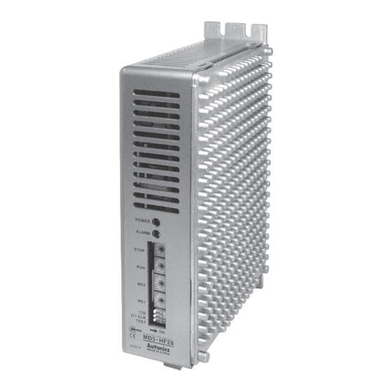
MD5 Series
Small, Light, High Speed & Torque 5-Phase Stepper Motor Driver
Features
● Bipolar constant pentagon drive method
● Includes auto current down and self-diagnosis function
● Low speed rotation and high accuracy controlling with
microstep-driving (MD5-HD14, MD5-HF14, MD5-HF14-AO,
MD5-HF28)
[Max. resolution - 250 division / In case of 5-phase stepper
motor of which basic step angle is 0.72°, it enables to
control up to 0.00288° per pulse and it requires 125,000
pulses per rotation.]
● Photocoupler input insulation method to minimize the
effects from external noise
Please read "Safety Considerations" in operation
manual before using.
Ordering Information
MD
5
H
F
Power supply
Step type (resolution)
Motor phase
Item
※ 1: Except MD5-ND14
Specifications
Model
MD5-HD14
Power supply
20-35VDCᜡ
Allowable voltage range
90 to 110% of the rated voltage
※
Max. current consumption
2
3A
※
RUN current
3
0.4-1.4A/Phase
STOP current
27 to 90% of RUN current (set by STOP current switch)
Drive method
Bipolar constant current pentagon drive
Basic step angle
0.72˚/step
Resolution
1, 2, 4, 5, 8, 10, 16, 20, 25, 40, 50, 80, 100, 125, 200, 250-division (0.72 to 0.00288 /Step)
Pulse width
Min. 1㎲ (CW, CCW), Min. 1ms (HOLD OFF)
Duty rate
50% (CW, CCW)
Rising/Falling time Below 130ns (CW, CCW)
Pulse input voltage [H]: 4-8VDCᜡ, [L]: 0-0.5VDC
Pulse input current 7.5-14mA (CW, CCW), 10-16mA (HOLD OFF, DIVISION SELECTION, ZERO OUT)
Max. input pulse
Max. 500kHz (CW, CCW)
※
frequency
5
270Ω (CW, CCW),
Input resistance
390Ω (HOLD OFF, DIVISION SELECTION),
10Ω (ZERO OUT)
Insulation resistance
Over 100MΩ (at 500VDC megger, between all terminals and case)
Dielectric strength
1000VAC 50/60Hz for 1min (between all terminals and case)
±500V the square wave
Noise immunity
noise (pulse width: 1μs)
by the noise simulator
Mechanical
1.5mm amplitude at frequency 5 to 60Hz (for 1 min) in each X, Y, Z direction for 2 hours
Vibration
Malfunction
1.5mm amplitude at frequency 5 to 60Hz (for 1 min) in each X, Y, Z direction for 10 min
Ambient temp. 0 to 40℃,
Environ-
storage: -10 to 60℃
ment
Ambient humi. 35 to 85%RH, storage: 35 to 85%RH
Approval
ᜢ
Approx. 327.5g
※
6
Weight
(approx. 220g)
※
1: When using over 30VDC power supply, torque characteristics are improved but the driver temperature raise. The unit should be installed at the well ventilation
environment.
※
2: Based on ambient temperature 25℃, ambient humidity 55%RH.
※
3: RUN current varies depending on the input RUN frequency and max. RUN current at the moment varies also varies depending on the load.
※
4: In case of MD5-HF14-AO, MD5-ND14, there are no DIVISION SELECTION, ZERO OUT function.
※
5: Max. input pulse frequency is max. frequency to be input and is not same as max. pull-out frequency or max. slewing frequency.
※
6: The weight includes packaging. The weight in parenthesis is for unit only.
5-Phase Stepper Motor Driver
14
No mark Zero point excitation output
Output
AO
Alarm output
RUN current
14
1.4A/Phase
28
2.8A/Phase
D
20-35VDC
F
100-220VAC
H
Micro step (250-division)
N
Normal Step
5
5-Phase
MD
Motor Driver
MD5-HF14
※
1
100-220VACᜠ 50/60Hz
±2kV the square wave noise (pulse width: 1μs) by the noise simulator
0 to 50℃, storage: -10 to 60℃
ᜢ
Approx. 840g
(approx. 680g)
MD5-HF14
MD5-HF28
※ 1
※ KR-55MC can be replaced with MD5-HD14.
※ KR-5MC can be replaced with MD5-ND14.
※ MD5-MF14 can be replaced with MD5-HF14.
※ KR-505G can be replaced with MD5-HF28.
MD5-HF14-AO
MD5-HF28
5A
1.0-2.8A/Phase
※
270Ω (CW, CCW),
270Ω (CW, CCW),
390Ω (HOLD OFF,
390Ω (HOLD OFF),
DIVISION SELECTION),
10Ω (ALARM)
10Ω (ZERO OUT)
ᜢ
ᜢ
Approx. 820g
Approx. 1.35kg
(approx. 660g)
(approx. 1.2kg)
※
Environment resistance is rated at no freezing or condensation.
MD5-HD14
MD5-ND14
MD5-HF14-AO
(only for MD5-HF14,
MD5-HF28 model)
MD5-ND14
※
1
20-35VDCᜡ
3A
0.5-1.5A/Phase
25 to 75% of RUN
current (set by STOP
current volume)
1, 2-division (0.72, 0.36/step)
Min. 10㎲ (CW, CCW),
Min. 1ms (HOLD OFF)
4
Max. 50kHz (CW, CCW)
390Ω
(CW, CCW, HOLD OFF)
±500V the square wave
noise (pulse width: 1μs)
by the noise simulator
0 to 40℃,
storage: -10 to 60℃
ᜢ
Approx. 183g
(approx. 130g)
(A)
Photoelectric
Sensors
(B)
Fiber
Optic
Sensors
(C)
Door/Area
Sensors
(D)
Proximity
Sensors
(E)
Pressure
Sensors
(F)
Rotary
Encoders
(G)
Connectors/
Connector Cables/
Sensor Distribution
Boxes/Sockets
(H)
Temperature
Controllers
(I)
SSRs/Power
Controllers
(J)
Counters
(K)
Timers
(L)
Panel
Meters
(M)
Tacho/
Speed/Pulse
Meters
(N)
Display
Units
(O)
Sensor
Controllers
(P)
Switching
Mode Power
Supplies
(Q)
Stepper Motors
& Drivers
& Controllers
(R)
Graphic/
Logic
Panels
(S)
Field
Network
Devices
(T)
Software
Q-3
Advertisement

Related Manuals for Autonics MD5 Series


Summary of Contents for Autonics MD5 Series
- Page 1 5-Phase Stepper Motor Driver MD5 Series Small, Light, High Speed & Torque 5-Phase Stepper Motor Driver Photoelectric Features Sensors ● Bipolar constant pentagon drive method ● Includes auto current down and self-diagnosis function Fiber Optic ● Low speed rotation and high accuracy controlling with...
- Page 2 MD5 Series 5-Phase Micro Stepper Motor Driver [MD5-HD14] Unit Description Resolution switch RUN current switch STOP current switch Input Power indicator Motor terminal Function Power Zero connection ※ Refer to page Q-3 for terminal selection output terminal the specifications. DIP switch...
- Page 3 (input power max. 24VDC, input current 10-20mA) BLUE Blue Gray+Red Software Yellow+Black Motor ORANGE Orange Orange+White GREEN Green Brown+Green ※ This connection cable color is only for Autonics motors. BLACK Black Blue+Purple It may different cable color when using other motors. Power [Power] 20-35VDC...
- Page 4 MD5 Series Connections POWER 20-35VDC Division selection Black signal Green Zero point ※ Please refer to Q-40 for Orange excitation User Motor standard wiring. output signal Controller Blue Dimensions (unit: mm) 76.5 39.5...
- Page 5 5-Phase Stepper Motor Driver (1.4A/Phase, AC Power) 5-Phase Micro Stepper Motor Driver [MD5-HF14] Photoelectric Unit Description Sensors Resolution STOP current switch Function selection DIP switch switch RUN current switch Fiber Alarm indicator (red) Optic Input Sensors Power indicator terminal Door/Area Sensors Proximity Sensors...
- Page 6 (input power max. 24VDC, input current 10-20mA) ORANGE Orange Orange+White Motor Green Brown+Green GREEN ※ This connection cable color is only for Autonics motors. Black Blue+Purple BLACK It may different cable color when using other motors. [Power] 100-220VAC Power 50/60Hz...
- Page 7 5-Phase Stepper Motor Driver (1.4A/Phase, AC Power) Connections Photoelectric Sensors Fiber Optic Sensors Door/Area Sensors Blue Proximity F.G. Sensors Orange Motor 100-220VAC 50/60Hz Green Black Pressure Sensors ※ Please refer to Q-40 for Rotary standard wiring. Encoders Division selection Connectors/ signal Connector Cables/ Zero point excitation...
- Page 8 MD5 Series 5-Phase Micro Stepper Motor Driver [MD5-HF14-AO] Unit Description STOP current switch Function selection DIP switch RUN current switch Alarm indicator (red) Input/Output Power indicator Resolution switch terminal Motor Power connection terminal terminal ※ Refer to page Q-3 for the specifications.
- Page 9 Gray+Red Yellow+Black Field Network Devices Motor ORANGE Orange Orange+White Green Brown+Green GREEN Software ※ This connection cable color is only for Autonics motors. Black Blue+Purple BLACK It may different cable color when using other motors. [Power] 100-220VAC Power 50/60Hz Q-11...
- Page 10 MD5 Series Connections Blue F.G. Orange Motor Green 100-220VAC 50/60Hz Black ※ Please refer to Q-40 for Alarm standard wiring. 3-5VDC output User Controller Dimensions (unit: mm) 4-M4 Tap Depth: 8 133.5 Q-12...
- Page 11 5-Phase Stepper Motor Driver (2.8A/Phase, AC Power) 5-Phase Microstep Motor Driver [MD5-HF28] Photoelectric Unit Description Sensors Resolution switch RUN current switch Fiber STOP current switch Optic Sensors Door/Area Sensors Proximity Sensors Pressure Power indicator Function Sensors selection Alarm indicator (red) DIP switch ※...
- Page 12 BLUE Blue Gray+Red Yellow+Black ORANGE Motor Orange Orange+White Green Brown+Green GREEN Black Blue+Purple ※ This connection cable color is only for Autonics motors. BLACK It may different cable color when using other motors. [Power] 100-220VAC Power 50/60Hz Q-14...
- Page 13 5-Phase Stepper Motor Driver (2.8A/Phase, AC Power) Connections Photoelectric Sensors Fiber Optic Sensors Door/Area Sensors Proximity F.G. Sensors 100-220VAC 50/60Hz Pressure Sensors Black Green Rotary Encoders Orange Motor Division selection Blue Connectors/ signal Connector Cables/ Zero point excitation Sensor Distribution Boxes/Sockets output signal ※...
- Page 14 MD5 Series 5-Phase Stepper Motor Driver [MD5-ND14] Unit Description Input Motor terminal Power connection RUN current terminal terminal volume Function selection STOP DIP switch current ※ Refer to page Q-3 for the specifications. volume Functions Function selection DIP switch Switch position...
- Page 15 Motor ORANGE Orange Orange+White Meters GREEN Green Brown+Green Tacho/ Speed/Pulse Meters ※ This connection cable color is only for Autonics motors. BLACK Black Blue+Purple It may different cable color when using other motors. Display Units Power Sensor [Power] Controllers 20-35VDC...
-
Page 16: Time Chart
MD5 Series Time Chart 1-pulse input method Rotation position 2-pulse input method Rotation position ※ Do not input CW, CCW signals at the same time in 2-pulse input method. It may not operate properly if another direction signal is inputted when one of CW or CCW is [H]. -
Page 17: Ordering Information
5-Phase Stepper Motor Driver (1.4A/Phase, DC Power, Multi-Axis) Low Noise, Low Vibration Multi Axis 5-Phase Stepper Motor Driver Photoelectric Features Sensors ● Simultaneous operation of 2, 3-axis by single power supply Fiber 20-35VDC Optic Sensors ● Small, light weight and advanced quality by custom IC and surface mounted circuit Door/Area Sensors... - Page 18 MD5 Series Functions Function selection DIP switch Switch position Name Function OFF (default) TEST Self diagnosis function 30rpm rotation Not use 1/2 CLK Pulse input method 1-pulse input method 2-pulse input method Auto Current Down Not use TEST Self diagnosis function is for motor and driver test.
-
Page 19: Unit Description
Orange+White ※ In case of standard connection, refer to Q-40 page. Meters GREEN Green Brown+Green ※ This connection cable color is only for Autonics motors. Tacho/ BLACK Black Blue+Purple It may different cable color when using other motors. Speed/Pulse Meters ※... - Page 20 MD5 Series Dimensions MD5-HD14-2X (unit: mm) 4-M3 Tap 2-axis 1-axis MD5-HD14-3X 4-M3 Tap 3-axis 2-axis 1-axis ※ Accessory connector specification Connector Qty. Accessory Manufacturer Model No. MD5-HD14-2X MD5-HD14-3X Power 2-wire housing Yeonho electronics YH396-02V Motor 5-wire housing Yeonho electronics YH396-05V...
- Page 21 ② The thickness of cable should be same or thicker than Speed/Pulse Meters the motor cable's when extending the motor cable. 7. Autonics motor driver does not prepare ③ Must separate between the signal cable and the power protection function for a motor. Display cable over 10cm.
Need help?
Do you have a question about the MD5 Series and is the answer not in the manual?
Questions and answers