Table of Contents
Advertisement
Quick Links
Advertisement
Table of Contents

Related Manuals for Sygonix 2380477


Summary of Contents for Sygonix 2380477
- Page 1 Operating Instructions RFID access system Item no. 2380477...
-
Page 2: Table Of Contents
Table of contents Page Introduction ................................4 Explanation of symbols ............................4 Intended use ................................5 Delivery content ..............................5 Safety information ..............................6 a) General information ............................6 b) Battery safety information ..........................7 Controls and connections ............................8 Installation and connection ..........................9 a) Installation ..............................9 b) Connecting to conventional voltage/power supply ..................10 c) Connecting to alarm system ........................10 d) Wiegand interface ............................ - Page 3 Page 11. Troubleshooting ..............................25 12. Cleaning and maintenance ..........................27 13. Disposal ................................27 a) Product ................................27 b) (Rechargeable) batteries ..........................27 14. Declaration of Conformity (DOC) ........................27 15. Technical data ..............................28 a) Access system .............................28 b) IR remote control ............................28...
-
Page 4: Introduction
1. Introduction Dear customer, Thank you for purchasing this product. This product complies with statutory, national and European regulations. To ensure that the product remains in this state and to guarantee safe operation, always follow the instructions in this manual. These operating instructions are part of this product. -
Page 5: Intended Use
3. Intended use This product is designed to prevent unauthorised access to doors (e.g. in an office) and to activate/disable alarm systems. The product enables to save up to 2000 users with different transponders. Holding a paired transponder in front of the reading surface activates a potential-free relay changeover contact (see contact rating under “Technical data”). -
Page 6: Safety Information
5. Safety information Damage caused due to failure to observe these instructions will void the warranty. We shall not be liable for any consequential damage! We shall not be liable for damage to property or personal injury caused by incorrect handling or failure to observe the safety information! Such cases will void the warranty/guarantee. -
Page 7: B) Battery Safety Information
b) Battery safety information • Keep batteries out of the reach of children. • Do not leave batteries lying around in the open; there is a risk of them being swallowed by children or pets. If swallowed, consult a doctor immediately, it could be fatal! •... -
Page 8: Controls And Connections
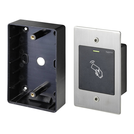
6. Controls and connections 1 Opening for wall mounting 2 LED indicator 3 RFID sensor The brightness sensor on the back serves as a tamper protec- tion. The IR reception LED (not visible from the outside) is located right next to the LED indicator (2). Connection cables: Colour Inscription... -
Page 9: Installation And Connection
7. Installation and connection Ensure that the connection cables are not kinked or squashed. This can cause malfunctions, short circuits and device defects. Ensure that no cables or wires are damaged when drilling holes or tightening screws. Installation and connection may only be carried out when power supply is switched off. Make sure that the brightness sensor on the back is not exposed to light beams after installation, as switch- ing on the system could cause activation of tamper protection with subsequent locking of all functions. -
Page 10: B) Connecting To Conventional Voltage/Power Supply
b) Connecting to conventional voltage/power supply When a conventional power supply unit should be used, observe the following figures with the wiring diagram. A) “Fail-secure” door opener: Releases the locking latch only when its operating voltage is applied (common design for front doors). -
Page 11: D) Wiegand Interface
d) Wiegand interface There are two application options for the Wiegand interface of the access system: 1) The access system is used as an external card reader The access system can be connected to a compatible Wiegand controller and used as an external card reader. The Wiegand controller must support a 26-bit protocol that is used for the transmission of transponder data. -
Page 12: Operation
8. Operation a) IR remote control The IR remote control is factory supplied with a pre-inserted battery. Remove a small transparent protective strip that prevents early discharge of the battery and the IR remote control is ready for use. The battery must be changed when the access system no longer responds to the IR remote control. To do this, take out the battery holder at the lower end of the IR remote control and replace the depleted CR2025 battery with a new one. -
Page 13: Programming
9. Programming Important! We recommend that you note all settings. You will thus be able to refer to them over time and adapt them to new requirements. You should note access data such as user name, memory cell number, transponder number, etc. to know who can access the system. -
Page 14: B) Changing The Master Code
b) Changing the master code Access system programming always requires the master code, which should be selected accordingly. The default master code is “123456” (the same applies after resetting the code lock to factory defaults). For security reasons, we strongly recommend that you change this master code immediately after programming when the access system is in normal operation. - Page 15 User transponder is automatically saved in the next free memory cell: This pairing procedure enables quick and easy pairing of new user transponders in the next free memory cell. However, a specific user transponder that is defective or lost can only be deleted via the transponder number and not via the memory cell number, as the memory cell number to which this specific user tran- sponder is assigned is unknown.
- Page 16 Multiple user transponders with consecutive transponder numbers are saved at a time This option enables you to save multiple transponders with consecutive transponder numbers at the same time. Since the memory cell numbers are also consecutive, transponders can be assigned to them; moreover, it is possible to delete an individual transponder that is defective or lost via the memory cell number.
- Page 17 2) Pairing a user transponder with the master transponder This pairing procedure enables quick and easy pairing of new user transponders in the next free memory cell. However, a specific user transponder that is defective or lost can only be deleted via the transponder number and not via the memory cell number, as the memory cell number to which this specific user tran- sponder is assigned is unknown.
-
Page 18: D) Deleting Individual User Transponders
d) Deleting individual user transponders The respective user will no longer have access once the corresponding user transponder has been deleted. User transponders can be deleted via the user transponder, the transponder number or the memory cell number. User transponders can also be deleted with the master transponder. 1) Deleting a user transponder with the IR remote control •... -
Page 19: E) Deleting All User Transponders
e) Deleting all user transponders • Enable the programming mode as described in section 8. a); the LED starts to flash red. • Enter the programming code to delete the transponders. The yellow LED will then light up. • Enter the master code again. •... -
Page 20: G) Enabling Or Disabling Protection Against Incorrect Entries
g) Enabling or disabling protection against incorrect entries This function allows you to program whether or not the access system should react to 10 or more consecutive incor- rect entries with a lock (by default: disabled). Proceed as follows: • Enable the programming mode as described in section 8. a); the LED starts to flash red. •... -
Page 21: I) Enabling/Disabling Led Indications And Beeps
i) Enabling/disabling LED indications and beeps Function and error messages of the access system are accompanied by LED indications and beeps. They can be enabled and disabled (default setting: LED indications and beeps are enabled) Proceed as follows: • Enable the programming mode as described in section 8. a); the LED starts to flash red. •... - Page 22 1) Resetting the access system and paring master transponder • De-energise the access system and wait for the LED to go off. • Press and hold down the door opener button. • Energise the access system. The access system will emit two beeps. Now release the door opener button. •...
-
Page 23: Operation
10. Operation a) Getting started Power on the access system once it has been connected and installed. After powering on, the access system will emit a beep and the red LED will glow steadily (standby). The access system is now ready for use and can be programmed. If the access system continuously emits beeps with the LED flashing quickly, it means that the brightness sensor on the back has activated tamper protection and disabled all functions. -
Page 24: B) Accessing Via Valid User Transponder
b) Accessing via valid user transponder Once the access system has recognised a valid user transponder, the changeover contact and door opener are acti- vated for a preset time and the green LED lights up. When the time is up, the red LED lights up (standby). After enabling the toggle mode (as described in section 8. -
Page 25: Troubleshooting
11. Troubleshooting The access system retains its settings and is ready for operation after a power outage. However, the access system will not work during a power failure. For safety reasons, we recommend that you connect the access system to an uninterruptible power supply (as in case of an alarm system) depending on the application. - Page 26 Transponder is not recognised • Make sure you hold one transponder in front of the RFID sensor at a time (see section 6, clause 3). • Ensure the transponder is close enough (approx. 3 cm) to the access system. • Only EM transponders with a frequency of 125 kHz can be used. •...
-
Page 27: Cleaning And Maintenance
12. Cleaning and maintenance This product does not require maintenance. Use a dry, lint-free cloth for occasional cleaning. In case of heavy soiling, lightly moisten the cloth with water. Never use aggressive detergents, rubbing alcohol or other chemical solutions, as they can cause discolouration or erase button inscriptions. -
Page 28: Technical Data
15. Technical data a) Access system Power supply ........12 - 18 V/DC Power consumption ......Standby <50 mA Frequency band ........124.6 - 125.4 kHz Transmission power......11.62 dBm Max. reading distance ......approx. 3 cm Data retention in case of a power cut ...yes Suitable transponders ......Commercially available EM transponders for frequency 125 kHz Output ...........Potential-free single-pole changeover contact (relay) Max. - Page 32 This is a publication by Conrad Electronic SE, Klaus-Conrad-Str. 1, D-92240 Hirschau (www.conrad.com). All rights including translation reserved. Reproduction by any method, e.g. photocopy, microfilming, or the capture in electronic data processing systems require the prior written approval by the editor. Reprinting, also in part, is prohibited. This publication represent the technical status at the time of printing.
Need help?
Do you have a question about the 2380477 and is the answer not in the manual?
Questions and answers