Table of Contents
Advertisement
Quick Links
Advertisement
Table of Contents

Related Manuals for Sygonix 1385634


Summary of Contents for Sygonix 1385634
- Page 1 Operating instructions Digital room thermostat Item No. 1385634...
-
Page 2: Table Of Contents
Table of contents Page 1. Introduction .................4 Explanation of symbols .............5 3. Intended use ................6 4. Scope of delivery ..............7 5. Features ................8 Safety information .............8 a) Persons/Product ..............8 b) Batteries ................ 11 7. Installation .................13 8. Inserting or replacing the batteries .........17 9. - Page 3 Page 10. Settings ................23 a) Temperature calibration ..........23 b) Time setting ..............24 c) Setting the economic temperature ......24 d) PROGRAMME setting ..........25 11. Setup ..................26 12. Error messages display ............30 13. Maintenance and cleaning ..........31 14. Disposal ................33 a) Product ................33 b) Batteries ................33...
-
Page 4: Introduction
1. Introduction Dear Customer, thank you for purchasing this product. This product complies with the statutory national and Euro- pean requirements. To maintain this status and to ensure safe operation, you as the user must observe these operating instructions! These operating instructions are part of this product. They contain important notes on commissioning and handling. -
Page 5: Explanation Of Symbols
2. Explanation of symbols The lightning symbol is used when your health is at risk. This symbol points out particular dangers associated with handling, function or operation. The arrow symbol indicates special advice and opera- ting information. Observe the operating instructions! -
Page 6: Intended Use
3. Intended use The digital room thermostat serves automatic switching of a connected end device, according to the set or programmed times or the set temperatures. The room thermostat must only be operated with commer- cial batteries of type AAA/Micro. It is intended for indoor use only. -
Page 7: Scope Of Delivery
4. Scope of delivery • Room thermostat • 2x AAA batteries • 2x screws • Operating instructions Up-to-date operating instructions: 1. Open www.conrad.com/downloads in a browser or scan the displayed QR code. 2. Select document type and language and enter the item number into the search field. After submitting the query you can down- load displayed records. -
Page 8: Features
5. Features • Manual mode; AUTO mode; PROGRAMME mode • Display • Programmable thresholds • Frost protection function • Lock function 6. Safety information The guarantee/warranty will expire if damage is in- curred resulting from non-compliance with the oper- ating instructions! We do not assume any liability for consequential damage! We do not assume any liability for property damage and personal injury caused by improper use or non-compli-... - Page 9 • The product is not a toy. Keep the product away from children. Therefore, be particularly careful when chil- dren are present. • The product must not be exposed to extreme tem- peratures, strong vibration, strong moisture or strong mechanical strain. The product must not be- come damp or wet.
- Page 10 • The following unfavourable conditions are to be avoided at the place of use and during transport: - Dust or flammable gases, fumes or solvents - Strong vibration, impact or blows • Handle the product with care. It can be damaged by impact, blows or when dropped even from a low height.
-
Page 11: B) Batteries
• In commercial institutions, the accident prevention regulations of the Employer’s Liability Insurance As- sociation for Electrical Systems and Operating Mate- rials are to be observed. • If you have questions which remain unanswered by these operating instructions, please contact us or an- other expert. - Page 12 • If not used for a longer period (e.g. in case of stor- age), remove the inserted batteries. If batteries are too old, they may leak and cause damage to the product, which leads to the cancellation of the war- ranty/guarantee! Read the “Disposal”...
-
Page 13: Installation
7. Installation The room thermostat must only be installed by a qual- ified specialist. Installation must only be performed ac- cording to the applicable local provisions. The room thermostat must not be installed near any windows, doors, heat sources or ventilation openings. Also avoid installation in locations where the device is exposed to direct sunlight. - Page 14 Check the mains supply line for voltage-freeness. Ensure that no present electrical or water lines are damaged during installation. The same applies, if only low voltage is to be supplied through the relay, since this may cause short circuit at in- stallation! Remove the battery holder at the bottom of the device.
- Page 15 The installed relay is potential-free. The connection ex- ample shows the connection to mains voltage 230 V/ AC. Observe the maximum contact resilience; see chap- ter “Technical Data” and the operating instructions of the device that is to be controlled via the room thermo- stat, on how to set up the circuits.
- Page 16 Push the upper shell onto the base plate (figure 2). Make sure that the supply lines are not crushed or damaged by this. The upper shell is now attached to the base plate again with the housing screw (figure 3). ...
-
Page 17: Inserting Or Replacing The Batteries
8. Inserting or replacing the batter- • Pull the battery holder from the bottom of the device. • Insert the two batteries of type AAA (Micro) in the correct polarity. Observe the marking in the battery compartment holder. • Return the battery holder to the room thermostat. •... -
Page 18: Commissioning And Operation
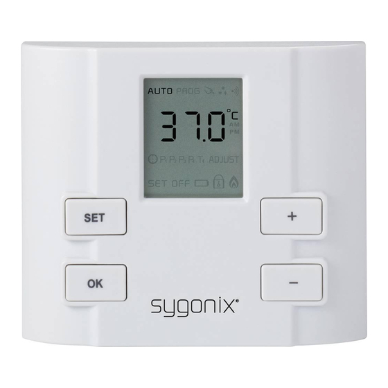
9. Commissioning and operation Observe Chapter “Safety information”! Manual mode PROGRAMME Mode Frost protection function AUTO Mode Icon Time/temperature display Display Celsius Display AM / PM Symbols for switching times ECONOMIC temperature Symbol for time setting Display calibration Display off LOCK function Heating/consumer on Display SET... -
Page 19: B) Selection Of The Operating Function
b) Selection of the operating function Switch on the room thermostat. Push the button OK repeat- edly until the desired operating function (manual mode; frost protection function; AUTO mode; PROGRAMME mode) is displayed. c) Manual operation Manual operation serves constant increase or reduction of the room temperature. -
Page 20: D) Auto Mode
d) AUTO mode The following values are set ex works for AUTO mode. 00:00——06:00 Temperature setting: 18 °C 06:00——08:00 Temperature setting: 20 °C 08:00——18:00 Temperature setting: 16 °C 18:00——22:00 Temperature setting: 20 °C 22:00——24:00 Temperature setting: 18 °C In AUTO mode, the symbol “AUTO” is displayed. The temperature value set ex works can be changed for the current heating or reduction phase. -
Page 21: E) Programme Mode
e) PROGRAMME mode Set the switching times and temperatures as described in item “PROGRAMME setting” . Then switch the room thermo- stat to PROGRAMME mode. The symbol “AUTO PROG” is displayed. The programmed temperature value can be changed manu- ally for the current heating or reduction phase. Briefly push the plus + or minus - button. -
Page 22: F) Frost Protection Function
f) Frost protection function When the frost protection function is active, the room ther- mostat will prevent the room temperature to drop below 5 °C. The frost protection function thus prevents freezing of liq- uid-based heatings and pipes. The frost protection temper- ature is fixed at 5 °C in the factory and cannot be changed. -
Page 23: Settings
10. Settings The thermostat must be on. Push the buttons SET and OK at the same time to get to the setting mode. The relay switches off in setting mode. Change the values with the buttons “+” and “-” . Keep the re- spective button pressed for quick adjustment. -
Page 24: B) Time Setting
The settings are only applied with the next temperature measurement of the thermostat. This may take a while. b) Time setting The time is set in 12-hour format (midnight to noon = AM / noon to midnight = PM). Push SET Push SET Push OK Push SET and OK... -
Page 25: D) Programme Setting
d) PROGRAMME setting Set the desired start, end times and temperatures for the pro- gramme mode here. The connected consumer is switched on and off by remote control after this time. Two switching periods can be programmed. Keep SET and OK Push plus + or minus - Push the plus + or minus - buttons pushed for... -
Page 26: Setup
11. Setup To switch to the setup settings, the thermostat must be in the position OFF . Switch Push the OK Keep SET and OK to the button buttons pushed To set the next To set the to confirm for 5 seconds parameters setting parameters... - Page 27 Order Descrip- Note Setting Display tion options 0 °C Difference 0.2 °C between 0.5 °C activation 1.0 °C and deac- tivation Factory 1.5 °C tempera- setting ture 2.0 °C (Switch- 2.5 °C 3.0 °C hystere- 3.5 °C sis) 4.0 °C Temper- ature display...
- Page 28 open closed Switching The relay condition switch- of the es at a relay room (contact temper- NO and ature COM) in below the OFF condition 5 °C (factory setting) (factory Lock func- setting) tion (key lock)
- Page 29 10°C - 35°C Max. (adjust- adjustable able in Display room steps of at 35°C tempera- 0.5°C / ture factory setting 35°C) param- eters to factory setting Indi- Factory vidual Setting parame- ters to be main- tained (setting works)
-
Page 30: Error Messages Display
12. Error messages display The display flashes when the room temperature drops be- low 0 °C or climbs above 45 °C. -
Page 31: Maintenance And Cleaning
13. Maintenance and cleaning Regularly check the technical safety of the device, e.g. for a damaged casing. If you have reason to believe that the device can no longer be operated safely, disconnect it immediately and make sure it is not operated unintentionally. It must be assumed that safe operation is no longer possible •... - Page 32 Only qualified experts familiar with the hazards involved and the relevant regulations must perform repairs. The product requires no servicing apart from replacing the rechargeable battery. Servicing or repair must only be car- ried out by a specialist or specialist workshop. Therefore, never open it (except for the procedures described in these operating instructions for insertion/replacing the batteries).
-
Page 33: Disposal
14. Disposal a) Product Electronic devices are recyclable waste and must not be disposed of in household waste! Dispose of the product according to the applicable statutory provisions at the end of its service life. Remove any inserted batteries and dispose of them separately from the product. -
Page 34: Technical Data
You thus fulfil your statutory obligations and contribute to the protection of the environment. 15. Technical data Operating voltage ..... 3.0 V/DC (2x 1.5 V micro bat- teries, type AAA) Switching output ...... max. 230 V/AC / 8 A (ohmic load) / 3.5 A (inductive load) / relay potential-free / NO a. - Page 36 o Legal Notice This is a publication by Conrad Electronic SE, Klaus-Conrad-Str. 1, D-92240 Hirschau (www.conrad.com). All rights including translation reserved. Reproduction by any method, e.g. photocopy, mi- crofilming, or the capture in electronic data processing systems require the prior written approval by the editor.
Need help?
Do you have a question about the 1385634 and is the answer not in the manual?
Questions and answers