
Related Manuals for WoodFast M305X


Summary of Contents for WoodFast M305X
- Page 1 Wood Lathe Instruction Manual Model: M305X FOR YOUR SAFETY READ ALL INSTRUCTIONS CAREFULLY BEFORE USING THIS MACHINE Ver. QCR-07-93-40...
-
Page 2: Table Of Contents
How best to use your electronic speed control unit..................9 How best to use your electronic speed control unit..................9 Troubleshooting............................11 Explosion Diagram..........................12 Parts List...............................13 Specifi cations Model Number M305X Swing Over Bed 305mm Swing Over Tool Rest Base 240mm Working Distance Between Centers 406mm... -
Page 3: Contents Of Package
Contents of Package Unpacking and Checking Contents Unpack your lathe from its carton and check to see that you have all of the following items. Do not turn your machine ON if any of these items are missing. You may cause injury to yourself or damage to your machine. -
Page 4: Getting To Know Your Lathe
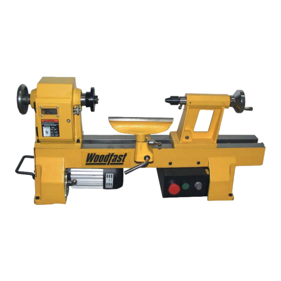
Getting to Know Your Lathe Lifting handle Handwheel Tool rest base Face plate Tool holder Spur center Motor Tool rest Lathe bed Live center Tailstock locking lever Tail stock Switch Tailstock handwheel Tool rest base locking lever Tailstock spindle locking arm Indexing / Spindle lock Assembly The machine must not be plugged in and the power switch must be in the OFF position until the... -
Page 5: Attaching The Live Center
Knockout Bar Knockout bar The knockout bar is used to remove the spur center from the headstock spindle. Insert knockout bar into hole at opposite side from spur center. (See Fig.04) Fig.04 Attaching Live Center On the Tailstock Insert the live center, with a No. 2 Morse Taper shank into the tailstock spindle. -
Page 6: Adjustments And Operations
Secure Lathe to a Solid Work Surface The lathe must be attached to a solid work surface or stand. Four mounting holes are easily accessible at the base of the lathe. (See Fig.09) Mounting holes Fig.09 Adjustments and Operations Adjusting the Tool Rest Tool rest The tool rest base can be easily moved along the lathe bed. -
Page 7: Changing Spindle Speeds
Changing Spindle Speeds Headstock pulley Access cover The lathe features three step motor and Headstock spindle pulleys. These three drive ratios are used in conjunction with the electronic variable speed control to provide maximum power and speed when required. 1, Open both motor pulley and Headstock pulley access Motor pulley Access cover doors. -
Page 8: Indexing/Spindle Lock
The lathe can be set up for a faceplate turning operation. The work piece should be “rough cut” as close as possible to fi nished shape before mounting. (See Fig.16) Indexing/Spindle Lock The dual purpose Indexing / Spindle lock is positioned at the front of the Headstock for ease of use. -
Page 9: Electrical Requirements
Eletrical Requirements In the event of a malfunction or breakdown, grounding provides a path of least resistance for electric current to reduce the risk of electric shock. This tool is equipped with an electric cord having an equipment-grounding conductor and a grounding plug. The plug must be plugged into a matching outlet that is properly installed and grounded in accordance with all local codes and ordinances. -
Page 10: How Best To Use Your Electronic Speed Control Unit
All belt positions may not be required for general woodturning operations. Woodfast Electronic Speed Control The Electronic Speed Control Unit has been factory set for normal woodturning use. These settings can be adjusted to suit your own personal preference in line with the precedures shown below. - Page 11 - press enter and Maximum Frequency is displayed - set to 130Hz - press ENT and display fl ashes once to confi rm change - press ESC twice until drC is displayed - use up arrow and SET is displayed - press enter and ACC is displayed - use up/down arrow keys until HSP is displayed - press enter and High Speed Setting is displayed...
-
Page 12: Troubleshooting
Troubleshooting IMPORTANT: When carrying out any adjustments turn off switch and make sure electrical leads are disconnected from mains power. PROBLEM POSSIBLE CAUSE THE CURE Excessive vibration Out of balance work Reduce spindle speed. Prepare wood to a true circle before loading into lathe. Point of holding may not be centralised. -
Page 13: Explosion Diagram
Explosion Diagram... -
Page 14: Parts List
Parts List Ref No. Description Ref No. Description Handwheel Locknut M8 Bearing Hex. Socket head screw Wave washer Spring washer 6 Retaining ring Belt tension handle Spindle head Locking arm Spindle lock pin Motor Spring Pan head screw Spindle lock tube Switch box Spindle lock nut Pan head screw...
Need help?
Do you have a question about the M305X and is the answer not in the manual?
Questions and answers