
Related Manuals for WoodFast M320


Summary of Contents for WoodFast M320
- Page 1 Instruction Manual WOOD LATHE M320 IMPORTANT For your safety, read instructions carefully before assembling or using this product. Save this manual for Original Instruction future reference. V.1-201507...
-
Page 2: Table Of Contents
INDEX GENERAL INFORMATION FOREWORD MACHINE IDENTIFICATION CUSTOMER SERVICE RECOMMENDATIONS SAFETY PRECAUTIONS SAFETY REGULATIONS RESIDUAL RISKS SAFETY AND INFORMATION SIGNALS SPECIFICATIONS MAIN COMPONENTS TECHNICAL SPECIFICATION ELECTRICAL CONNECTION NOISE LEVEL INSTALLATION INSTALL TOOL REST AND BASE ON LATHE BED SPINDLE LOCK ATTACHING SPUR CENTER ON THE HEADSTOCK KNOCKOUT BAR ATTACHING LIVE CENTER ON THE TAILSTOCK INSTALL THE FACEPLATE TO THE HEADSTOCK... -
Page 3: General Information
1. GENERAL INFORMATION FOREWORD Some information and illustrations in this manual may difer from the machine in your possession, since all the configurations inherent in the machine complete with all the optionals are described and illustrated. Therefore, refer only to that information strictly connected with the machine configuration you have purchased. -
Page 4: Safety Precautions
2. SAFETY PRECAUTIONS SAFETY REGULATIONS Read carefully the operation and maintenance manual before starting, using, servicing and WARNING carrying out any other operation on the machine. The manufacturer disclaims all responsibilities for damages to persons or things, which might be caused by any failure to comply with the safety regulations. -
Page 5: Residual Risks
RESIDUAL RISKS Despite observance of all the safety regulations, and use according to the rules described in this manual, residual risks may still be present, among which the most recurring are: - contact with tool - contact with moving parts (belts, pulleys, etc..) - recoil of the piece or part of it - accidents due to wood splinters or fragments - tool insert ejection... -
Page 6: Specifications
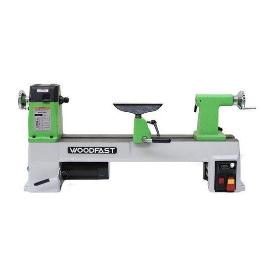
3. SPECIFICATIONS MAIN COMPONENTS 1-Tailstock locking lever 8-Face plate 2-Tailstock handwheel 9-Spindle's top 3-Tail stock 10-Tool rest base 4-Locking handle 11-Tool rest 5-Live center 12-Lathe bed 6-Spindle wheel 13-Lock lever 7-Headstock 14-Electrical box TECHNICAL SPECIFICATION Rated voltage 230V/50HZ Rated current Motor power input 750W Swing over bed diameter... -
Page 7: Electrical Connection
3.3 ELECTRICAL CONNECTION - Electrical installation should be carried out by competent, qualified personnel. - The mains connection should be made using the terminal box. - Replacement of the power supply cable should only be done by a qualified electrician. WARNING To avoid electrocution or fire, any maintenance or repair to electrical system should be done only by qualified electricians using genuine replacement parts. -
Page 8: Installation
4. INSTALLATION WARNING The machine must not be plugged in and the power switch must be in the OFF position untill installation is complete. 4.1 INSTALL TOOL REST AND BASE ON REST LOCK BUTTON TOOL SLIDE BEARING LATHE BED - Remove the tailstock assembly by releasing the locking handle and sliding the assembly off the end of the lathe bed. -
Page 9: Knockout Bar
4.4 KNOCKOUT BAR TOP BAR - The knockout bar is used to remove the spur center from the headstock spindle. Insert knockout bar into hole at opposite side from spur center. Fig.4.4 4.5 ATTACHING LIVE CENTER ON THE TAILSTOCK HAND WHEEL TAILSTOCK TAILSTOCK SPINDLE - Insert the live center, with a No.2 Morse Taper shank... -
Page 10: Secure Lathe To A Solid Work Surface
4.8 SECURE LATHE TO A SOLID WORK SURFACE MOUNTING HOLES - The lathe must be attached to a solid work surface or stand. Four mounting holes are easily accessible at the base of the lathe. Fig.4.8 5. ADJUSTMENTS AND OPERATIONS 5.1 ADJUSTING THE TOOL REST TOOL SLIDE BEARING REST... -
Page 11: Maintenance
6. MAINTENANCE CAUTION! BEFORE CLEANING OR CARRYING OUT MAINTENANCE WORK, DISCONNECT THE MACHINE FROM THE POWER SOURCE (WALL SOCKET). NEVER USE WATER OR OTHER LIQUIDS TO CLEAN THE MACHINE. USE A BRUSH. REGULAR MAINTENANCE OF THE MACHINE WILL PREVENT UNNECESSARY PROBLEMS. - Keep the lathe bed casting clean and lubricated. - Page 12 8. DIAGRAMS & COMPONENTS 74 75 76 15 16 10 11 13 14 19 20 21 52 53 54 55 56 57 40 58 59 42 43 44 45 46 48 49 61 62 63...
- Page 13 Description Part No. QTY. Description Part No. QTY. Description Part No. QTY. 1 Bed JMWL1203010002A 32 Self-locking nut M10GB889B 63 Plate JMWL1203020014 2 Hexagon socket cap screw M6X30GB70B 33 Locking lever JMWL1203050004 64 Cross pan head screw M4X16GB819B 3 Flat washer WSH6GB97D1B 34 Retaining ring CLP21GB894D1B...
Need help?
Do you have a question about the M320 and is the answer not in the manual?
Questions and answers