Table of Contents
Advertisement
Quick Links
Advertisement
Table of Contents

Related Manuals for Circor IMO OptiLine ACE3


Summary of Contents for Circor IMO OptiLine ACE3
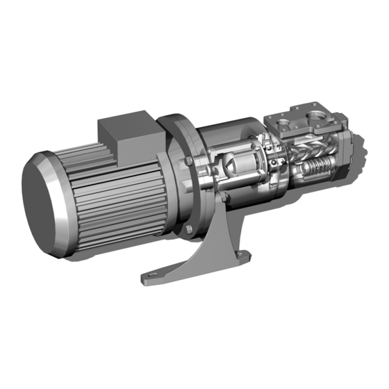
- Page 1 Opti Line ACE3 Screw pump Maintenance & Start up Instruction...
-
Page 2: Table Of Contents
Contents Installation Transport and storage ............................3 Lifting of pump ..............................3 Pipe connections ..............................4 Suction line ................................4 Discharge line ..............................4 Deaeration ................................4 Strainer ................................5 Liquid trap ................................5 Gauges ................................6 Pressure relief valve ............................6 Pressure testing and flushing .......................... -
Page 3: Installation
Installation BEFORE COMMENCING ANY WORK, READ THIS INSTRUCTION CAREFULLY! Design limitations and technical data for each pump are found in the Product description. Installation of an IMO AB ACE pump does not require special skills. However, these instructions presume that the work is carried out by experienced fitters. -
Page 4: Pipe Connections
Measures shall be provided to avoid accidental contact with the outer magnetic rotor. Pipe connections The pipe work shall be installed and supported so that no pipe stresses are transfered to the pump body. The pipe work should be tight in order to avoid leakage and infiltration of foreign particles and/or air. -
Page 5: Strainer
Strainer The pump has to be protected from foreign matter, such as weld slag, pipe scale, etc., that could enter the pump via the suction line. If the cleanliness of the system cannot be guaranteed, a strainer must be installed in the inlet pipe near the pump. -
Page 6: Gauges
Gauges Gauges for monitoring the pump’s working conditions are recommended. These gauges should be placed readable as close to the pump’s in- and outlet flanges as possible. On standard pumps, series ACE there are gauge connections for both in and outlet. Pressure relief valve All systems with screw pumps must be equipped with a pressure relief valve installed immediately adjacent to... -
Page 7: Start-Up
Start-up Before starting After installation and whenever it can be assumed that the pump has been emptied, the pump must be thor oughly filled with liquid. See fig 11. Make sure the prime mover is locked out and can not be started accidentally. Rotate the shaft by hand while filling the pump, to ensure that the rotor bores and magnetic couplings are Fig. -
Page 8: Trouble Shooting
Trouble shooting Problem Cause What to do Wrong direction of Electric cables to motor wrongly con Reverse the terminal connection on electric rotation nected. motor. Connecting and disconnecting of electric cables must be done only by personnel authorized to do such work. The pump cannot be ... - Page 9 Disturbance Cause What to do Pressure too high The pressure relief valve is set too Readjust the pressure relief valve. high. The oil is too cold (or has higher vis Reduce the pressure setting until opera cosity than anticipated). tional temperature has been reached.
-
Page 10: Components
Components List of components Valid for all pumps in sizes: ACE 025/032/038 Rotor diameter and Generation: D3/L3/K3/N3 With version codes: { N The version code is composed of the letters in the 4 columns. Example of pump designations std: ACE 025L3 NKBP Components included in spare parts set Denomination Qty G012... -
Page 11: Exploded View
Exploded view 124A 462A 520A 1020 007B 998B (501A) 998A 463A (608A) 006A (608) (6120) (613) (615) 701A (614) 5010 703B 703A 702A Ordering code Part numbers for pump size Recommendation: For maintenance the following spare Item Spare Parts sets part sets are recommended: G012 Rotor set Dlead ... -
Page 12: Sectional View
Sectional view www.imo.se... -
Page 13: Service And Maintence
Service and maintence Service intervals The intervals for inspection and replacement of wear parts vary greatly with the properties of the pumped liquid and can only be determined by experience. Pumping liquid which contains abrasive materials, or liquid that is corrosive, will significantly reduce service life and call for shorter service intervals. -
Page 14: Useful Tools
Useful tools A = Puller F = Screw driver B = Screw spanner 16 mm G = Plier C = Plastic mallet H = Guide pins D = Allen keys (3 mm & 5 mm) = Oil can E = Mounting sleeve, D=25,5 mm Magnetic coupling M = Screws (006A) S = Sealing can... - Page 15 Mount guide pins (H) Dismount the pump. Be careful with the mag- netic force the first 5 cm Dismount can screws (R) using the Allen key Remove the Sealing can (S) (non-magnetc) Remove the oring 007B Remove the retaining ring (T) www.imo.se...
- Page 16 Remove the inner magnetic rotor (U) Lift cover 520. (Not valid for size 038) Remove cover 520 and oring 520A Remove cover screws 451 and dismount front cover 5010 and gasket 506 Remove power rotor 1020 and idler rotors 202 Remove retaining ring 124 and support wash...
- Page 17 Release spring tension by turning valve spin dle 608 CCW as much as possible. Loosen and remove screws 453. Separate the valve element from the rear cover 551. If neces Dismount ball bearing 122 and balancing sary, replace the gasket 556 and the oring bush 351 006A Remove screws 702 between connection...
-
Page 18: Reassembly
Reassembly Attach the drive hub 998 using washer 998A Place the outer magnetic rotor (Q) on the and screw 998B drive hub (N) Attach the outer magnetic rotor (Q) using Fit the connection frame 003 on top and fas screws 006A and nonmagnetic Allen key ten the washers 702A and screws 702 Fit the gasket 556 in place and fit the valve elements thin end (608) in place in the rear... - Page 19 Reinsert the idler rotors 202 and the power Place gasket 506 and front cover 5010 and rotor 1020 into the pump tighten screws 451 Place the oring 520A, cover 520, inner mag netic rotor (U) and the retaining ring (T) back Place the oring 007B and then the sealing in position cup (S) and tighten all screws (R)
- Page 20 Adress: IMO AB PO Box 42090, 126 14 Stockholm Sweden...
Need help?
Do you have a question about the IMO OptiLine ACE3 and is the answer not in the manual?
Questions and answers