Table of Contents
Advertisement
Quick Links
Centrifugal Pump with
Volute Casing
Original Operating Manual
Version
BA-2021.06 en-US
146-900/E
ID-No.
550 113
NI series
ALLWEILER GmbH
Postfach 1140
Allweilerstr. 1
78301 Radolfzell
Germany
Phone: +49 (0)7732-86-0
Fax: +49 (0)7732-86-436
E-mail: service@allweiler.de
Internet: http://www.allweiler.com
We reserve the right to make technical changes.
Read carefully before use.
Retain for future use.
Advertisement
Table of Contents
Troubleshooting

Related Manuals for Circor ALLWEILER NI Series


Summary of Contents for Circor ALLWEILER NI Series
- Page 1 Centrifugal Pump with Volute Casing Original Operating Manual NI series Version BA-2021.06 en-US ALLWEILER GmbH 146-900/E Postfach 1140 ID-No. 550 113 Allweilerstr. 1 78301 Radolfzell Germany Phone: +49 (0)7732-86-0 Fax: +49 (0)7732-86-436 E-mail: service@allweiler.de Internet: http://www.allweiler.com We reserve the right to make technical changes. Read carefully before use.
-
Page 2: Table Of Contents
Table of contents Table of contents About this document ....... 5.2.4 Optimizing cross-section and direction changes . - Page 3 Table of contents 9.2.1 Stub shaft diameter at the shaft seal ..39 9.2.2 Ambient conditions ......39 9.2.3 Sound pressure levels .
- Page 4 Table of contents List of figures List of tables Fig. 1 Type plate (example) ......10 Tab. 1 Target groups and their duties .
-
Page 5: About This Document
About this document About this document This manual • Is part of the pump • Applies to the afore-mentioned pump series • Describes safe and appropriate operation during all oper- ating phases Target groups Target group Duty Operating company Keep this manual available at the site of operation of the system, including for later use. -
Page 6: Warnings And Symbols
About this document Warnings and symbols Warning Risk level Consequences of disregard Immediate acute risk Death, serious bodily harm DANGER Potentially acute risk Death, serious bodily harm Potentially hazardous situation Minor bodily harm CAUTION Potentially hazardous situation Material damage NOTE Tab. -
Page 7: Safety
Safety Safety The manufacturer does not accept any liability caused by • Pumps used with water as the pumped liquid must not be disregarding the entire documentation. used for foodstuffs or drinking water. Use of the pump for foodstuffs or drinking water must be specified in the order data sheet. -
Page 8: Obligations Of Personnel
Safety Qualified personnel 2.2.3 Obligations of personnel • Make sure all personnel tasked with work on the pump • All directions given on the pump must be followed (and kept have read and understood this manual and all other appli- legible), e.g. -
Page 9: Specific Hazards
Safety Specific hazards 2.3.1 Explosion hazard area • (→ ATEX additional instructions). 2.3.2 Electric shock In case of contact with live parts (for example, cables in the ter- minal box of the electric motor) there is a risk of electric shock resulting in serious injuries or death. -
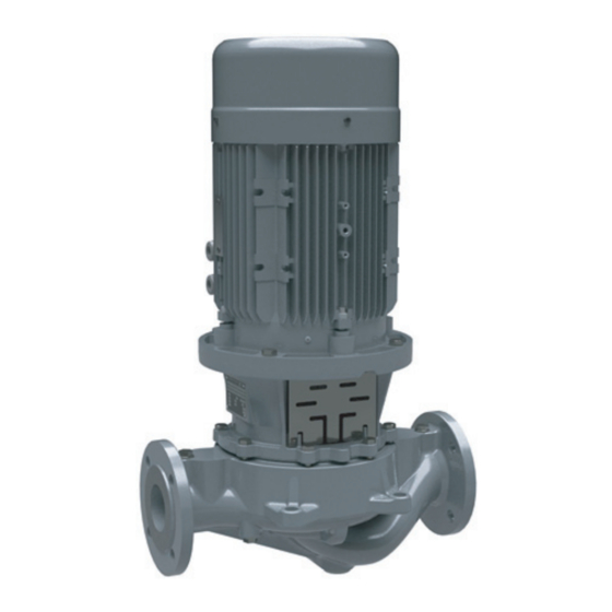
Page 10: Layout And Function
Layout and function Layout and function Labels 3.1.2 Digital nameplate The digital nameplate is an additional plate and contains a 3.1.1 Type plate machine-readable pump identification number. The num- ber is a globally unique identifier for this pump. Kreiselpumpe 12345678 Typ: _________________________ Q = ____ m³/h NPSH = ____... -
Page 11: Pump Type Code
Layout and function 3.1.3 Pump type code NI 40 - 200 / 01 / 180 U3D - S - W3 - 38 / 300 Fig. 4 Pump type code (example) Series Size (standard nominal diameter) Nominal impeller diameter Hydraulic number Actual impeller diameter [mm] Shaft seal Mounting type (optional) -
Page 12: Layout
Layout and function Layout Fig. 5 Layout Motor with fixed bearing at drive end Limit for heat insulation Shaft seal Motor bell housing Impeller Guard sheet Stub shaft Volute casing Shaft seals 3.3.1 Mechanical seals Mechanical seals have functional leaks. Only one of the following shaft seals can be used. -
Page 13: Auxiliary Systems
Layout and function Auxiliary systems 3.4.1 Sealing systems Quenching Fig. 6 Single mechanical gasket with depressurized quenching receptacle (sketch) Gasket Quench medium connection Quench space The pressure of the pumped fluid is higher than the pressure of the quench medium during quenching. The gasket surfaces are lubricated by the pumped fluid. -
Page 14: Transport, Storage And Disposal
Transport, storage and disposal Transport, storage and disposal Transport Preservation For weight specifications (→ documents for the particular Not necessary for non-rusting materials order). Contact the manufacturer for recommendations regarding preservatives. 4.1.1 Unpacking and inspection on delivery 1. Unpack the pump/aggregate on delivery and inspect it for NOTE transport damage. -
Page 15: Removing The Preservative
Transport, storage and disposal Removing the preservative Disposal Only necessary for pumps treated with preservative Plastic parts can be contaminated by poisonous or radioac- tive pumped media to such an extent that cleaning is insuf- ficient. WARNING WARNING Risk of poisoning from preservatives and cleaning agents Risk of poisoning and environmental damage by the in the foodstuffs and drinking water sector! pumped medium or oil! -
Page 16: Setup And Connection
Setup and connection Setup and connection For pumps in explosion hazard areas (→ ATEX additional 5.1.5 Checking the guard sheet alignment instructions). WARNING NOTE Risk of explosion due to incorrect guard sheet alignment! Heavy falling objects can deform the guard sheet and hit rotat- Material damage due to distortion or passage of electrical ing parts. -
Page 17: Specifying Pipe Lengths
Setup and connection 5.2.3 Specifying pipe lengths Avoid running empty For suction operation: install a foot valve in the suction pipe to prevent the pump and suction pipe from running empty during downtimes. Make provisions for isolating and shutting off the pipes For maintenance and repair work. -
Page 18: Installing Auxiliary Pipes (If Available)
Setup and connection 5.3.4 Installing auxiliary pipes (if available) Follow the manufacturers’ specifications for any available auxiliary systems. 1. Connect the auxiliary pipes to the auxiliary connections so that they are stress-free and do not leak (→ setup drawing). 2. To avoid air pockets, run the pipes with a continuous slope up to the pump. -
Page 19: Electrical Connection
Setup and connection 7. From stub shaft bore hole diameter 60 mm: insert the shaft 13. Install the safety equipment: key. – Guard sheet for the motor bell housing 8. Turn the motor shaft so that the slot of the stub shaft is 14. -
Page 20: Operation
Operation Operation For pumps in explosion-hazard areas (→ ATEX additional 6.1.5 Checking the direction of rotation instructions). NOTE Preparations for the initial start-up Material damage due to incorrect direction of rotation! Make sure the direction of rotation of the motor corre- 6.1.1 Identifying the pump type sponds to the arrow indicating the direction of rotation on... -
Page 21: Start-Up
Operation Start-up Shutting down 6.2.1 Switching on Take the following measures whenever the pump is shut down: Pump aggregate set up and connected properly All connections stress-free and sealed Pump is Measure Any available auxiliary systems are ready for operation ...shut down Perform measures accord- All safety equipment installed and tested for functionality... -
Page 22: Start-Up Following A Shutdown Period
Operation Start-up following a shutdown period 1. If the pump is shut down for over 1 year, take the following measures before starting it up again: Shutdown period Measure > 1 year For versions with roller bearings without lifetime lubrication: relubricate >... -
Page 23: Maintenance
Maintenance Maintenance For pumps in explosion-hazard areas (→ ATEX additional 7.2.2 Cleaning the pump instructions). NOTE Trained service technicians are available for fitting and repair jobs. Present a pumped medium certificate (DIN High water pressure or spray water can damage bearings! safety data sheet or safety certificate) when requesting Do not clean bearing areas with a water or steam jet. -
Page 24: Returning The Pump To The Manufacturer
Maintenance 7.3.1 Returning the pump to the manufacturer 7.3.3 Removal of the flanged motor Pump unpressurized WARNING Pump completely empty Electrical connections isolated and motor secured against Risk of injury due to overturning motor! switch-on Secure the motor to prevent overturning before working on Pump cooled down the stub shaft. -
Page 25: Installing
Maintenance Tighten the jack screw with a screwdriver without applying 7.4.2 Installation of the flanged motor any excessive force. NOTE 3. Widening the stub shaft (220.xx): – Screw the M10 x 40 or M12 x 40 jack screw (not Damage due to incorrect installation! included in the scope of delivery) into the stub shaft. -
Page 26: Ordering Spare Parts
Maintenance 10. Turn the stub shaft by hand: – Ensure the stub shaft can be turned easily without pres- sure points. Ordering spare parts For trouble-free replacement in the event of faults, we rec- ommend keeping entire slide-in units or spare pumps avail- 0 mm able on site. -
Page 27: Troubleshooting
Troubleshooting Troubleshooting For faults which are not specified in the following table or can- not be traced back to the specified causes, please consult the manufacturer. Possible faults are identified by a fault number in the table below. This number identifies the respective cause and rem- edy in the troubleshooting list. - Page 28 Troubleshooting Fault number Cause Remedy – – – – – Viscosity or specific gravity of the pumped Consult the manufacturer. medium outside the range specified for the pump – – – – – – Geodetic differential head and/or pipe flow Remove sediments from the pump resistances too high and/or pressure pipe.
-
Page 29: Troubleshooting List
Troubleshooting Fault number Cause Remedy – – – – – – – – Lubricant: excessive, insufficient or Reduce, top up or replace the lubricant. unsuitable – – – – – – – Connecting bolts not tightened properly Tighten the connecting bolts. –... -
Page 30: Appendix
Appendix Appendix Part no. Designation Sectional drawings 514.01 Threaded ring 9.1.1 Auxiliary connections 515.01 Clamping ring 525.01 Spacer sleeve Abbreviation Connection 565.01 Rivet Pumped medium / emptying 672.01 Vent Filling 686.01 Guard sheet Filling / Bleeding 686.02 Guard sheet Leak egress 710.01 Pipe Pressure gauge... -
Page 31: Sectional Drawings
Appendix Part no. Designation 940.01 Shaft key 970.09 Additional plate (digital nameplate) 971.01 Type plate Tab. 14 Designations of components according to part numbers 9.1.3 Sectional drawings Fig. 12 U3...D – Unbalanced mechanical seal – sizes with diameter 16 at the shaft seal optional 550 113 –... - Page 32 Appendix 220.01 515.01 914.06 Fig. 13 Stub shaft version with clamping ring NI series BA-2021.06 en-US 550 113 – 146-900/E...
-
Page 33: With Diameter 30 At The Shaft Seal
Appendix Fig. 14 U3...D – Unbalanced mechanical seal – sizes with diameter 30 at the shaft seal optional ** optional, from motor size 225 mandatory 550 113 – 146-900/E BA-2021.06 en-US NI series... -
Page 34: 40-250, 50-250 And 65/-200
Appendix 920.01 902.01 412.01 Fig. 15 Sizes with shaft diameter 24 at the shaft seal 686.01 Fig. 16 Attachment of the guard sheet to the motor bell housing 901.01 161.01 901.02 400.02 Fig. 17 Version with housing cover 360-250, sizes 40-250, 50-250 and 65/-200 NI series BA-2021.06 en-US... -
Page 35: Seal, Non-Cooled, Unbalanced Mechanical Seal
Appendix Fig. 18 Two-stage sizes with diameter 30 at the shaft seal, non-cooled, unbalanced mechanical seal optional ** optional, from motor size 225 mandatory 550 113 – 146-900/E BA-2021.06 en-US NI series... - Page 36 Appendix 220.01 515.01 914.06 Fig. 19 Stub shaft version with clamping ring 920.02 902.02 901.02 161.01 400.02 Fig. 20 Housing cover version (sizes 2/40-250 and 2/50-250) NI series BA-2021.06 en-US 550 113 – 146-900/E...
-
Page 37: With Diameter 40 At The Shaft Seal
Appendix Fig. 21 U3...D – Unbalanced mechanical seal – sizes with diameter 40 at the shaft seal optional 550 113 – 146-900/E BA-2021.06 en-US NI series... -
Page 38: 65-315, 80-315 And 100/-315
Appendix 400.01 901.01 400.02 901.02 509.01 Fig. 22 Version with intermediate ring for sizes 65-400 901.01 161.01 901.02 400.02 Fig. 23 Version with housing cover 470-315, sizes 65-315, 80-315 and 100/-315 686.01 Fig. 24 Attachment of the guard sheet to the motor bell housing NI series BA-2021.06 en-US... -
Page 39: Technical Specifications
Appendix Technical specifications 9.2.2 Ambient conditions Operation under other ambient conditions should be More technical specifications (→ order data sheet). agreed with the manufacturer Tempera- Relative humidity [%] Setup 9.2.1 Stub shaft diameter at the shaft seal ture [°C] height Long-term Short-term above sea... -
Page 40: Tab
Appendix 9.2.4 Tightening torques Part no. Thread size Quality Tightening torque [Nm] 901.01 901.02 901.10 901.11 901.12 902.01/ 920.01 903.01 G ¼ 903.02 G ⅜ 903.03 G ½ 903.04 904.05 914.06 12.9 914.10 M12 x 1.5 M16 x 1.5 922.01 1.4404 M20 x 1.5 M24 x 1.5... -
Page 41: Maximum Flange Loads
Appendix 9.2.6 Flange loads Definition of the pipe forces and torques on the basis of EN ISO 5199. Fig. 25 Flange loads at the pump Nominal Forces [N] Torques [Nm] flange diameter ∑F ∑M [mm] 1303 1035 1050 1637 1107 1125 1250 1025... -
Page 42: Spare Parts For Two Years Of Continuous Operation
Appendix Spare parts for two years of continuous operation according to DIN 24296 Part no. Part designation Number of identical pumps (including stand-by pumps) 6 or 7 8 or 9 > 9 Set/quantity of spare parts Guide wheel (all two-stage 171.01 pump sizes) 220.01... -
Page 43: Declaration Of Harmlessness
This declaration of harmlessness must be attached clearly visible outside of the packaging of the return shipment, and if possible sent in advance by e-mail including the safety data sheet, if applicable, to: service-emea-gr@circor.com. Please understand that return shipments without a declaration of harmlessness cannot be processed until such declaration is received. -
Page 44: Declaration Of Conformity According To Ec Machine Directive
Appendix Declaration of conformity according to EC Machine Directive The following declaration does not contain serial numbers or signatures. The original declaration is delivered with the respective pump. EC declaration of conformity according to machine directive, appendix II A ALLWEILER GmbH, Postfach 1140, 78301 Radolfzell, Germany; Tel. +49 (0)7732 86-0, Fax. +49 (0)7732 86-436 hereby declare that the pump unit/pump: Designation Equipment no.
Need help?
Do you have a question about the ALLWEILER NI Series and is the answer not in the manual?
Questions and answers