Table of Contents
Advertisement
Quick Links
Advertisement
Table of Contents

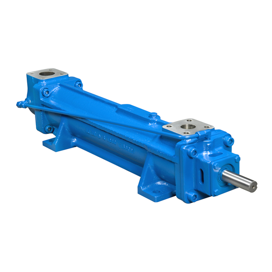
Summary of Contents for Circor IMO G12D S-137 Series
- Page 1 PRODUCT SERVICE MANUAL _G12D_ _(S)-137 and 350 PUMPS WARNING This Instruction Manual and General Instructions Manual, SRM00046, should be read thoroughly prior to pump installation, operation or maintenance. Manual No. SRM00125 JULY, 2020 Rev. 01 (20-0051)
-
Page 2: Table Of Contents
READ THIS ENTIRE PAGE BEFORE PROCEEDING FOR SAFETY OF PERSONNEL AND TO PREVENT DAMAGE TO EQUIPMENT, THE FOLLOWING NOMENCLATURE HAS BEEN USED IN THIS MANUAL: DANGER Failure to observe precautions noted in this box can result in severe bodily injury or loss of life. -
Page 3: General Instructions
A. GENERAL INSTRUCTIONS The instructions found herein cover the disassembly, assembly and parts identification of _G12D_-137 and 350 pumps. NOTE: Individual contracts may have specific provisions that vary from this manual. Should any questions arise which may not be answered by these instructions, refer to the General Instructions Manual, SRM00046, provided with your order. -
Page 4: Ordering Instructions
Figure 1 – Model Designator Definitions E. ORDERING INSTRUCTIONS When corresponding with Imo Pump regarding Series _G12D_-137 and 350 pumps, refer to pump nameplate, this instruction manual, and assembly drawing as instructed below: 1. From pump nameplate, record pump model number, serial number, and manufactured date. 2. - Page 5 F.2 OPERATING LIMITS CAUTION ATTENTION Operating conditions, such as speed, fluid viscosity, temperature, inlet pressure, discharge pressure, filtration, duty cycle, drive type, mounting, etc., are interrelated. Due to these variable conditions, specific application limits may be different from operational limitations. Equipment must not be operated without verifying system operating requirements are within pump’s capabilities.
-
Page 6: Parts List
G. PARTS LIST Table 2 – Pump Parts List DESCRIPTION DESCRIPTION Case Bearing Retainer Inlet Head Inboard Cover Cap Screws Bearing Retainer Hex Bolts (Qty. 16 on 350 Size) Pipe Plug Seal Seat Adapter (137 C-Face Steel Case Only) Pin Stop Ball Bearing Fastener Seal Power Rotor... - Page 7 H.2 TOOLS REQUIRED Procedures described in this manual require common mechanics hand tools, a torque wrench, dial indicators for alignment and a suitable lifting device such as slings, straps, etc. H.3 Pump Disassembly Procedure CAUTION Fluid leakage from disassembly of pump may make floor slippery and cause personal injury NOTE: To service mechanical seal and ball bearing only, perform H.3, steps 1 thru 5 and H.4, Steps 13 through 18.
- Page 8 4. Disassemble power rotor (63) as follows (See Figure 1 for seal drawings) : a. Using a flat nosed tool, such as a screw driver, remove both snap rings (42) from groove in power rotor (63). b. Sealed ball bearing (49) is assembled to power rotor (63) with light press fit. Ball bearing (49) may be removed by using bearing puller or vertical arbor press.
- Page 9 15. Remove housings (73, 24) by continuing to push them out through discharge end of the case (1). Remove and discard housing O-ring (28). Remove tubes (26) and O-rings (27) from housings (24 or 73). Discard O-rings (27) CAUTION ATTENTION Do not permit housings (73, 24) to drop as they are removed from pump.
- Page 10 14. Install O-ring (28) on balance piston housing (22). Install balance piston housing (22) onto inboard cover (46) being sure that roll pin in balance piston housing (22) mates to slit in inboard cover (46). 15. Install inboard cover (46) / balance piston housing (22) assembly in case with bolts (90) being sure that seal drain (70) in inboard cover (46) is positioned at 12 o-clock.
-
Page 11: Troubleshooting
23. Install thrust plate assembly including thrust plate (29), bolts (102) and spacers (101) on housing (73). Torque bolts (102) to value on appropriate assembly drawing. 24. Install gasket (9) in groove in inlet head (2), and install inlet head (2) on case (1) using hex bolts (4). - Page 12 CIRCOR 1710 Airport Road PO Box 5020 Monroe, NC USA 28111.5020 Tel: +1.877.853.7867 Email: cc@circor.com Web: www.circorpt.com © 2020 CIRCOR Pumps North America, LLC. All rights reserved.


Need help?
Do you have a question about the IMO G12D S-137 Series and is the answer not in the manual?
Questions and answers