Table of Contents
Advertisement
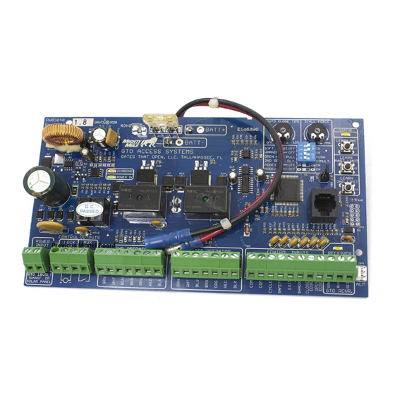
Generation-3 Control Board
Wiring and Programming Instructions
GTO/PRO 3000XL/4000XL
POWER
CONTROL
INPUTS
OUTPUTS
GTO
AUX
LOCK
TRANSF
PWR
RLY
18 VAC
GTO
AUX
or
LOCK
SOLAR
PRO3040-G3
FUSE
25
CHARGING
PWR IN
SLAVE CABLE
GRN
WHT
BLUE
BRN
ORG
RED
BLK
SLAVE INPUTS
for the
BATT+
BATT-
MASTER CABLE
GRN
WHT
BLUE
BRN
ORG
RED
BLK
MASTER INPUTS
1
AUTO CLOSE TIME
STALL FORCE
OFF
120
MIN
SOFT START OFF
ON
WARNING
OFF
ON
OPEN
PULL
PUSH
SLV OPEN
DLY.
SIMULT.
MODE1
OFF
ON
MODE2
OFF
ON
CONTROL INPUTS
COM COM
STATUS
LEARN RMT
MAX
S3
LEARN
MAST LIMIT
S2
LEARN
SLV LIMIT
S4
RECEIVER
GRN
BLK
RED
RECEIVER
ALM
Advertisement
Table of Contents

Related Manuals for GTO PRO3040-G3


Summary of Contents for GTO PRO3040-G3
- Page 1 Wiring and Programming Instructions GTO/PRO 3000XL/4000XL CHARGING PWR IN POWER CONTROL INPUTS OUTPUTS LOCK TRANSF SLAVE CABLE 18 VAC BLUE LOCK SOLAR SLAVE INPUTS PRO3040-G3 for the FUSE BATT+ BATT- MASTER CABLE BLUE MASTER INPUTS AUTO CLOSE TIME STALL FORCE...
- Page 2 Connecting Opener Power Cable Step 1 Make sure the control box power switch is in the OFF position. The ON/OFF Switch is located on the bottom of the control box. Remove the control box cover and slide the battery into position with its terminals to the RIGHT (see illustration).
-
Page 3: Powering The System
• All low voltage wire used with the GTO PRO® Gate Opener must be 16 gauge dual conductor, multi-stranded, direct burial wire (see page 20 and the Accessory Catalog). Do not run more than 1000 feet of wire. - Page 4 IMPORTANT INFORMATION ABOUT LOW VOLTAGE WIRE The only wire acceptable for use with GTO products is 16 gauge multi-stranded, low voltage, PVC sheathed wire. This particular gauge enables the transformer to provide an adequate charge through the control board to the battery at distances up to 1000 ft.
- Page 5 Step 7 Plug the transformer into the electrical outlet. (Use of a surge protector with the transformer is strongly recommended.) HINT: Keep a few mothballs in the control box to discourage insects from entering it and damaging the control board. Step 6 Strip "...
-
Page 6: Control Board Settings
CONTROL BOARD SETTINGS DIP Switches Main DIP Switch Settings (MODES) DIP Switch #1 - Soft Start/Stop ON - Soft start enabled (factory preset). OFF - Soft start disabled. The Soft Start/Stop feature slowly starts the gate as it begins to open and slows the gate as it comes to the closed position. - Page 7 Pull to Open Applications TURN CONTROL BOX ON Your GTO PRO® has two Limit Settings 1) OPEN Limit setting: (Gate in the OPEN POSITION / the limit is FACTORY SET and NOT ADJUSTABLE) The open limit setting is the fully open position.
- Page 8 Obstruction Sensitivity Potentiometer IMPORTANT: For safety reasons the obstruction setting or Stall Force on the GTO PRO® control board comes from the factory set at MIN (minimum). In many gate in- stallations this setting will need to be adjusted to overcome the weight and size of the gates.
-
Page 9: Setting Your Personal Transmitter Code
Setting Your Personal Transmitter Code All GTO transmitters are set to a standard code at the factory and are ready to operate your GTO PRO® Gate Opener your safety and security, however, we strongly recommend that you replace the factory setting with your own personal code. -
Page 10: Installing The Receiver
• Standard receiver cable length is 10 feet (receivers with a longer cable are available as special order items; call the GTO Sales Department). NEVER splice receiver cable! • Run the cable through PVC conduit to protect it from damage. - Page 11 PLEASE NOTE: Contact sensors are not included with the GTO PRO® 3000. The GTO PRO® 3000 is equipped with built-in obstruction sensitivity. The opener is designed to stop and reverse the gate within 2 seconds when it comes in contact with an obstruction. However, obstruction sensitivity, although functioning properly, may not be sensitive enough to prevent bodily injury in some circumstances.
- Page 12 If not installing a non-contact sensor skip to next section. PLEASE NOTE: Non-contact sensors are not included with the GTO PRO® 3000. The GTO PRO® 3000 can also accept "Safety" input from normally open "dry-contact" output devices such as photo beams connected to the SAFETY input terminal.
- Page 13 Connecting Accessories If not connecting accessories skip to next section. Cycle Input The GTO PRO® 3000 can accept NORMALLY OPEN "DRY-CONTACT" accessories, such as; Push Button Entry Devices and Key Pads. Refer to the sensor manufacturer’s instructions for information about installing these devices on a vehicular gate.
- Page 14 Connecting other devices to these terminals may cause incorrect operation and void your warranty. GTO Lock Connection: Connect the red and black leads from the lock to the GTO LOCK terminal on the GTO PRO® 3000 control board. Aux: • These 2 terminals are normally open 'dry-contact' (no voltage) relay ouput.
-
Page 15: Push To Open Installation
Push to Open Installation Step 4 Make sure the control box power switch is OFF. Use a small screwdriver to move the Number 3 DIP switch from the factory setting (OFF / Pull-To-Open) to ON for Push-To-Open. Turn power switch ON. The control board is now configured to push the gate open. - Page 16 Maintenance & Troubleshooting Guide If your gate opener does not function properly after it is installed, use this guide before calling the GTO Service Department. ‘PR03040-G3’ DIAGNOSTIC INDICATORS GUIDE This guide provides detailed explanations of various alarm sound and led indicators for the new PRO3040-G3 board).
- Page 17 Alarm: None ‘RECEIVER’ Led: blinking or OFF. • When the ‘RECEIVER’ led is blinking, the controller is receiving ‘GTO scheme’ 318 MHz signal from the receiver. This indicates that the transmitter and receiver are working properly. However, if the transmitter is not being pressed and the ‘RECEIVER’ led is blinking, this indicates that there is significant interference (i.e.
- Page 18 Alarm: 1 beep then 3 beeps with 2 seconds pause. ‘STATUS’ Led: 1 blink then 3 blinks with 2 seconds pause. • The master motor terminals and/or leads are shorted. The GTO, Inc. Technical Service Department is open Monday – Friday 8:00 Telephone (800) 543-1236 Telephone (850) 575-4144 Fax (850) 575-8950 •...
Need help?
Do you have a question about the PRO3040-G3 and is the answer not in the manual?
Questions and answers