Table of Contents
Advertisement
Quick Links
Advertisement
Table of Contents

Related Manuals for Biolase waterlase MDX 300


Summary of Contents for Biolase waterlase MDX 300
- Page 1 300/450 ALL-TISSUE LASER FOR DENTISTRY USER MANUAL...
- Page 2 Page Intentionally Left Blank...
-
Page 3: Table Of Contents
CONTENTS 5200999E REV. D\ Introduction …………………………………………………………. Section 1 Safety with the Waterlase ………………………………………… Precautions …………………………………………………………... Safety Instructions …………………………………………………... Plume Removal ……………………………………………………… Safety Features ……………………………………………………… Energy Monitor ……………………………………………………. Circuit Breaker ……………………………………………………. Keyswitch ………………………………………………………….. Footswitch …………………………………………………………. Remote Interlock Outlet ………………………………………….. Emergency Stop ………………………………………………….. Control Panel ………………………………………………………... - Page 4 Contents (continued) Optical Shaft ………………………………………………………. Protective Cover (for fiber optic shaft) ………………………….. Handpiece …………………………………………………………. Rear Plug ………………………………………………………….. Tip Plug ……………………………………………………………. Tip …………………………………………………………………... Tip Remover ………………………………………………………. Revolving Tip Holder ……………………………………………... Section 4 Operating Instructions ……………………………………………. Setup ………………………………………………………………….. Connect Unit to Operatory ……………………………………….. Filling the Internal Cooling Water Reservoir ……………………...
- Page 5 Contents (continued) Hard Tissue Procedures …………………………………………. Soft Tissue Procedures ………………………………………….. Curettage Procedures ……………………………………………. Fluid Entrapment and Air Embolism ……………………………. Root Canal Procedures ………………………………………….. Adjacent Structures ………………………………………………. Clinical Conditions ………………………………………………… Tissue Evaluation …………………………………………………. Tissue Contact and Tip Breakage ………………………………. Tip Changing ………………………………………………………. Water Splashing …………………………………………………...
- Page 6 Contents (continued) Soft Tissue Indications including Pulpal Tissues ……………… Root Canal Disinfection ………………………………………….. Section 8 Maintenance ………………………………………………………… Annual Maintenance ………………………………………………… Daily Maintenance …………………………………………………… Transportation ……………………………………………………….. Storage ……………………………………………………………….. Section 9 Calibration …………………………………………………………… Calibration Schedule ………………………………………………… Appendix A Labels …………………………………………………………………. Appendix B Accessories …………………………………………………………...
-
Page 7: Introduction
This manual provides instructions for use for trained dental surgeons and practitioners. When used and maintained properly, the Waterlase MDX will prove a valuable addition to your practice. Please contact your authorized local Biolase representative if you have any questions or require assistance. -
Page 8: Safety With The Waterlase
Periodically inspect eyewear for pitting and cracking. NOTE: For replacement or additional protective eyewear, please contact your authorized local Biolase representative. 4. Do not look directly into the beam or at specular reflections. 5. Direct the cutting spray toward targeted tissues only. -
Page 9: Plume Removal
The unit will not operate until the system is reset by pressing the “Next” button on the touch screen. If error messages persist please contact your authorized local Biolase representative. -
Page 10: Remote Interlock Outlet
1 and 5 of the connector. These contacts should have no voltage associated with them and should open on activation. Your authorized local Biolase service engineer can assist you in connecting the remote interlock to a door switch. -
Page 11: Installation Of The Waterlase Mdx
INSTALLATION INSTRUCTIONS Your local authorized Biolase representative will unpack the Waterlase MDX and your authorized Biolase service representative will install the unit. Please leave all crates and shipping containers unopened until your authorized trained service representative arrives. Complete installation, testing and demonstration requires approximately one full day. -
Page 12: Equipment Description
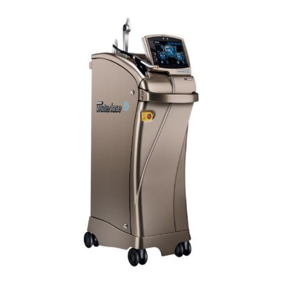
SECTION 3 EQUIPMENT DESCRIPTION GENERAL The Waterlase MDX dental laser system consists of two modules: • Optical Power Unit (the Unit – shown in Figures 2.1, 2.2 and 2.4) • Waterlase MDX Atomizing Delivery System (the Delivery System - shown – shown in Figures 3.3 and 3.4) OPTICAL POWER UNIT ELEMENTS Figures 3.1, 3.2 and 3.4 show the front, rear and top views of the unit. -
Page 13: Power Connection / Circuit Breaker
contacts connected to pins 1 and 5 of the connector. These contacts should have no voltage associated with them and should open on activation. Customers may request that the remote interlock be connected to a door switch. • Power Connection / Circuit Breaker—Attach power cord to unit at this location. The circuit breaker serves as a line switch to separate the unit from the main power supply (0 = OFF, 1 = ON). - Page 14 Figure 3.1: Front View Fiber Delivery System Telescopic Fiber Support Arm Touch Screen Control Panel Handpiece Front Handle Emergency Stop Switch Locking Wheels (front only) 5200999 Rev. D Waterlase MDX (01/14) 5200999 Rev. D Waterlase MDX (01/14)
- Page 15 Figure 3.2: Rear View Back Handle Self-contained Water System Ventilation Back Panel Remote Key Switch Interlock Outlet Footswitch Cable Wrap Plate Power Connection & Power Cable Circuit Breaker Wrap Plate Ground Pin Footswitch Support Footswitch Connector Bracket Air Inlet Connector...
-
Page 16: Waterlase Mdx Delivery System
Figure 3.4: Top View Trunk Fiber Water Bottle Cover Tray for Revolving Tip Holder Water Bottle Release Push Button Touch Panel Control System Front Handpiece in Handpiece Holder WATERLASE MDX DELIVERY SYSTEM (See Section 4 for detailed description and instructions) Delivery System Connection on the Unit The delivery system attaches to the unit via a multi-connector incorporating air, water, cooling air, illumination waveguides and the optical energy fiber optic. -
Page 17: Fiber Optic Cable
Fiber Optic Cable Fiber optic cable contains the optical fiber together with the illumination waveguides, air tubing and water tubing. Laser radiation is delivered from laser unit to the handpiece through the optical fiber. Protective Black Rubber Cap (for fiber optic connector) Protects input end of the fiber optic cable when not attached to unit. -
Page 18: Operating Instructions
SECTION 4 OPERATING INSTRUCTIONS SETUP Connect Unit to Operatory 1. Verify circuit breaker is in OFF position. 2. Verify keyswitch is in OFF position. 3. Connect power cord to unit (fig.2.2). 4. Verify minimum air pressure of 80 psi (5.5 bar) from air supply. 5. - Page 19 FIGURE 4.1 FIGURE 4.2 2. Locate internal water reservoir. Verify that white clip on the blue tube that is connected to the side of the water reservoir is closed; (fig 4.3) 3. Push button on the top connector and disconnect tubing from the lid; (fig. 4.4) FIGURE 4.3 FIGURE 4.4 4.
-
Page 20: Fill Self-Contained Water System Bottle
5. Use funnel to fill with distilled or deionized water to ¾’s full; FIGURE 4.7 6. Replace filter assembly and close lid tight; 7. Plug in water connector firmly, until it “clicks” in place; 8. Power up the system: • Switch the Power Circuit Breaker on the back panel ON; •... -
Page 21: Secure Fiber Optic Assembly To Unit
Be careful handling the water bottle assembly. Do not drop the parts. Any crack may cause damage when bottle is pressurized. SECURE FIBER OPTIC ASSEMBLY TO UNIT 1. Verify the Laser Head is centered to the top cover. If misaligned call Biolase headquarters for additional support;... - Page 22 FIGURE 4.12 FIGURE 4.13 2. Locate the hole on the left side of top view of laser unit and install telescopic fiber support arm; (fig. 4.13) 3. Take the new trunk fiber (fig. 4.14) from the accessories box and drape it around your neck;(fig.
- Page 23 FIGURE 4.16 FIGURE 4.17 6. Remove black and red protective cups from laser head and aperture (fig. 4.12 and 4.18); store all the cups for further use, do not lose them. 7. Carefully look inside the laser aperture (fig. 4.18) and check that surface of the protective window is clean, free of water, dirt or damage.
-
Page 24: Connecting Handpiece To Fiber Optic Cable
NOTE: You may need to move connector slightly to the sides to ensure proper engagement of all interfaces. DO NOT APPLY FORCE! WARNING: Applying force may create metal shavings or shave off the o-rings of the spray connector and cause damage of the laser head components. 9. - Page 25 3. Remove the fiber Protective Cover from the Fiber Shaft of the Trunk Fiber by pulling the cover off (fig. 4.25) and place it in the Handpiece Box; 4. Check the Fiber Shaft for any moisture and wipe off any that is found; NOTE: Check output end of the Fiber Shaft for any contamination of damage (see Sec.
-
Page 26: Disconnecting The Handpiece
DISCONNECTING THE HANDPIECE 1. Press “Change Handpiece” icon on the Touch Screen; 2. Press “Start” icon and wait until Delivery System is purged, watching the progress bar on the screen. WARNING: Failure to purge the handpiece prior to disconnecting may cause damage of the Fiber Delivery system. - Page 27 PROXIMAL DISTAL END END (INPUT (OUTPUT END) SHAFT PLASTIC FERRULE FIGURE 4.28 FIGURE 4.29 2. Remove the Tip Plug by pulling it out and place it in the Handpiece Box; 3. Remove Tip from the package (for new Tips only) and insert it into the Tip Remover or revolving Tip Holder.
- Page 28 FIGURE 4.32 FIGURE 4.33 WARNING: Be careful not to hit the proximal end of the Tip against the handpiece head and not to break retaining fingers of the plastic ferrule. 6. Slide the Handpiece laterally away from Tip Remover or Tip Holder. (fig. 4.34) FIGURE 4.34 NOTE: To remove the Tip, repeat the whole process in reverse order.
-
Page 29: Tip Inspection Instructions
TIP INSPECTION INSTRUCTIONS [01] Remove the tip from the handpiece and insert it into the correct side of the tip test Tip remover with t i p inside holder as shown using the tip remover. [02] Insert the tip test holder into the test adapter with the distal (or laser- emitting) end of the tip toward the microscope. -
Page 30: Operation
OPERATION CAUTION: Use of controls or adjustments and performance of procedures other than those specified herein may result in hazardous radiation exposure. Overview Before using the Waterlase MDX, be sure the system has been started appropriately, as described earlier in this manual. After the system has completed its startup process, turn the unit on by pressing the On/Off button. - Page 31 Language. Sound associated with the touch buttons can be adjusted. • Tip Type Selection menu—Allows selection of tip and handpiece appropriate to the chosen procedure. • Service Menu—Provides access to the system calibration and memory. Accessible only for authorized Biolase Field Service Engineers.
-
Page 32: To Start The Waterlase Mdx
TO START THE WATERLASE MDX 1. Verify that all connections have been properly secured 2. The Air supply must be connected and the external air pressure must be at 80 PSI (5.5 bar) or more. 3. Electrical input should be at least 100 VAC, maximum 15 amperes to 230VAC, 8 amperes. 4. -
Page 33: Modify And Save Preferred Values As Presets
MODIFY AND SAVE PREFERRED VALUES AS PRESETS The Waterlase MDX has sixteen pre-programmed presets stored on the system. The values of the presets, as well as additional combinations of presets, are presented in Section 7: Pre- programmed Pre-sets for General Hard and Soft Tissue Procedures. To select and store a new set of values and/or modes for Power, PPS, Water and Air, first select the values you wish to store from the system main menu. - Page 34 Press “Back” icon to return to the “Home screen”. Press the tip icon on the Home screen to access the Select Tip screen (below). On the “Select Tip” screen, all available tips for the Gold handpiece are displayed. When you select a tip, the calibration factor and expected power output appear on the “Gold Handpiece”...
-
Page 35: User Interface - General Navigation
USER INTERFACE - GENERAL NAVIGATION... -
Page 36: Error Messages
Standby mode and the screen will indicate the cause of the error and provide recommendations on clearing the error. If you cannot clear an error after following the directions on the error screen, please call your authorized local Biolase service representative for assistance. Corrective Error... -
Page 37: Waterlase Mdx Specifications
SECTION 5 WATERLASE MDX SPECIFICATIONS GENERAL Dimensions (W x L x H) • Unit 11 x 19 x 32 in (28 x 48 x 81cm) • With Fiber 11 x 19 x 40 in (28 x 48 x 102 cm) •... -
Page 38: Contraindications, Warnings And Precautions
SECTION 6 CONTRAINDICATIONS, WARNINGS AND PRECAUTIONS CONTRAINDICATIONS All clinical procedures performed with the Waterlase MDX must be subjected to the same clinical judgment and care as with traditional techniques. Patient risk must always be considered and fully understood before clinical treatment. The clinician must completely understand the patient’s medical history prior to treatment. -
Page 39: Hard Tissue Procedures
Hard Tissue Procedures All hard tissue (i.e. enamel, dentin, cementum and bone) procedures must be performed using air and water spray at appropriate settings. Failure to use the spray will result in tissue thermal damage. The long pulse settings (700 μs) are indicated only for soft tissue applications. Do not use long pulse settings to perform hard tissue procedures. -
Page 40: Adjacent Structures
or through the apex. Place the end of the tip ~2mm from the apex or away from being in contact with the wall of a curved canal. Activate the laser and spray only during the outward stroke when the fiber tip is pulled towards the coronal portion of the canal. For additional information on laser root canal enlargement, review the recommended clinical procedure presented in Appendix C, or the instructions provided with the EndoLase™... -
Page 41: Plume Removal
Plume Removal CAUTION: Laser plume may contain viable tissue particulates. Special care must be taken to prevent infection from the laser plume generated by vaporization of virally or bacterially infected tissue during procedures done with laser and minimal or no water spray. Ensure that all appropriate protective equipment (including high-speed suction to remove the plume, appropriately filtered masks, and other protective equipment) is used at all times during procedures with this laser device. -
Page 42: Clinical Applications
(5 mm away from targeted tissue), there will be minimal to no cutting effect. If the water spray is not flowing, or no distinct popping noise is present, stop the system immediately. Refer to the troubleshooting section of this Manual for instructions or call your authorized local Biolase representative for assistance. - Page 43 NOTE: Always remember that laser power and, therefore, hydrophotonic energy are delivered from the very end of the tip. Tissue cutting technique can be characterized as “end cutting,” whereas the mechanical drill is known as a “side cutting” instrument. Gently and slowly move the handpiece tip closer to the targeted tissue site. As you approach the treatment area you may notice a large accumulation of water.
-
Page 44: Presets For Soft And Hard Tissue Procedures
moving the tip along the tissue surface by applying light pressure. The incision will be noticed immediately after laser activation. Bleeding is controlled through reduction of the water setting. For superficial lesions or hemostasis, the tip must be placed out of contact at approximately 1-3 mm off the surface. -
Page 45: Calculating Emitted Power With Tip Attachment
CALCULATING EMITTED POWER WITH TIP ATTACHMENT: Example 1: Example 2: Tip Type: MZ4 Tip Type: RFT2 Calibration Factor: 0.90 Calibration Factor: 0.55 Display Power: 2W Display Power: 1W Then the Power Emitted is: Then the Power Emitted is: 2W x 0.90 = 1.80 W 1W x 0.55 = 0.55 W PRE-PROGRAMMED PRE-SETS FOR GENERAL HARD AND SOFT TISSUE PROCEDURES Sub-... -
Page 46: Tip Inspection
WARNING: Use of the damaged or contaminated Tip may cause damage of the Delivery System and will compromise clinical performance of the Waterlase MDX. Tips can be inspected using magnifying lenses, microscope, laser aiming beam or Biolase Tip Inspection Kit. -
Page 47: Basic Maintenance
2. While still in the “Ready” mode, check that the end of the tip does not “glow.” The red beam should not be visible when observed from the side (end of the tip must be dry); BASIC MAINTENANCE NOTE: This will not completely clean or sterilize the handpiece and tip. •... -
Page 48: Step 1-Cleaning Process
CAUTION: Use only MANUAL CLEANING described below. Other cleaning methods should be avoided since water entering the portals of the exhaust ring may damage the fiber optics inside the handpiece Step 1—Cleaning Process The cleaning process is intended to remove blood, protein and other potential contaminants, as well as to reduce the quantity of particles, microorganisms and pathogens present from the handpiece, laser tip surfaces and crevices. -
Page 49: Step 2-Sterilization Process
Tip removal using the Tip Remover or the Revolving Tip Holder • Slide the handpiece laterally toward the Tip Remover or Revolving Tip Holder • Place your thumb against the selected tip slot to prevent the laser tip from falling out of the Tip Holder when disconnecting it from the handpiece. - Page 50 Gravity Displacement 132°C (270°F) 15 minutes 15 – 30 minutes 132°C (270°F) Dynamic-Air-Removal 4 minutes 20 - 30 minutes (Pre-Vacuum) 134°C (EU only) 7. Upon completion of the cycle, the handpiece and tips must remain in the sterilization pouches until needed to maintain sterility. 8.
-
Page 51: Mirror Check And Cleaning
MIRROR CHECK AND CLEANING NOTE: If performance of the delivery system is questioned and the Tip is in good condition, check the Handpiece Mirror for damage or contamination. WARNING: Use of contaminated or damaged Mirror will cause damage of the Fiber Delivery System. -
Page 52: Mirror Alignment Check
4. Contaminated mirror can be cleaned and with cotton swab, moistened with optical grade acetone or alcohol: • Place wet swab over the mirror surface and wait for ~5sec for solvent to soften the contaminating material; • Wipe off the contamination by quick turn and removal of the swab; •... -
Page 53: Changing The Waterlase Mdx Handpiece Mirror
99.9% pure isopropyl alcohol is required for the use of this product. Please order from your authorized distributor (Biolase P/N 3000251). To insert and secure the NEW mirror into the handpiece, repeat whole procedure in reverse order. -
Page 54: Troubleshooting The Delivery System
TROUBLESHOOTING THE DELIVERY SYSTEM... -
Page 55: Fiber Check
FIBER CHECK NOTE: Regularly inspect the end of the Fiber Shaft. Always inspect and clean the Protective Window at the end of the Fiber Shaft after input end of the Tip or Handpiece mirror were damaged. WARNING: Use of dirty or contaminated Protective Window will cause damage of the Fiber Delivery System. -
Page 56: Waterlase Mdx Indications For Use
WATERLASE MDX INDICATIONS FOR USE IMPORTANT: Review all Contraindications, Warnings and Precautions presented in Section 6 before proceeding with using this device on patients. Use of Waterlase MDX may be indicated for: HARD TISSUE GENERAL INDICATIONS* • Class I, II, III, IV and V cavity preparation •... -
Page 57: Laser Periodontal Procedures
LASER PERIODONTAL PROCEDURES • Full thickness flap • Partial thickness flap • Split thickness flap • Laser soft tissue curettage • Laser removal of diseased, infected, inflamed and necrosed soft tissue within the periodontal pocket • Removal of highly inflamed edematous tissue affected by bacteria penetration of the pocket lining and junctional epithelium. -
Page 58: Soft Tissue Indications Including Pulpal Tissues
• Implant recovery • Incision and drainage of abscesses • Laser soft tissue curettage of the post-extraction tooth sockets and the periapical area during apical surgery • Leukoplakia • Operculectomy • Oral papillectomies • Pulpotomy • Pulp extirpation • Pulpotomy as an adjunct to root canal therapy •... -
Page 59: Annual Maintenance
The laser console contains electronic and mechanical components that are thoroughly checked when the unit is first shipped, as well as when an authorized Biolase engineer services the unit. Depending on the use of the unit, some of these components may require periodic servicing and/or replacement between annual maintenances. -
Page 60: Storage
Once crated, the unit should be transported by fork lift or pallet jack, and should never be laid on its side, dropped or banged. If you have any questions regarding transportation please call your authorized local Biolase representative. STORAGE The Waterlase MDX should be stored in a cool dry place when not in use. -
Page 61: Calibration
• Connect an output power meter to the laser, using a test fiber. The power meter head should be 1 to 2 inches from the fiber tip. • Using the software provided by Biolase, verify the test setup is complete. • Begin the calibration routine. The software will vary the unit’s output power settings and use the power readings from the meter to calibrate the power output monitoring settings. -
Page 62: Appendix A Labels
APPENDIX A LABELS Laser Hazard Symbol Location: Top cover of Laser head, directly above the Fiber Optic Connector. (Only visible during service) High Voltage Hazard Symbol (Only visible during service) Locations: • Top cover or Laser head, directly above the High Voltage input. - Page 63 Laser Explanatory Label INVISIBLE AND VISIBLE LASER RADIATION AVOID EYE OR SKIN EXPOSURE TO DIRECT OR Location: On top cover, adjacent to fiber SCATTERED INVISIBLE RADIATION CLASS 4 LASER optic connector PRODUCT Er, Cr: YSGG Laser System Wavelength 2.78 μm; Pulse energy: 450 mJ Max.
- Page 64 Remote Interlock Label Location: Back Panel ETL Listed Location: Back Panel Footswitch Label Location: Back Panel Emergency Stop Label Location: Front Covert Protective Earth Ground Location: Back Panel Attention (Small) Location: Back Panel WEEE Label Location: Back Panel...
- Page 65 Keyswitch Label Remote Label Identification Certification ETL Listing Electrical Rating Label Footswitch Label Air Intake...
- Page 66 Laser Aperature + Label Laser Explanatory Label...
-
Page 67: Appendix B Accessories
APPENDIX B ACCESSORIES KEYS REMOTE INTERLOCK FOOTSWITCH POWER CORD (USA) POWER CORD (EUROPE) AIR HOSE... -
Page 68: Appendix C Clinical Procedure Guidelines
APPENDIX C CLINICAL PROCEDURE GUIDELINES PERIODONTAL THERAPY CLINICAL PROTOCOL WARNINGS & PRECAUTIONS: Eyewear: Doctor, patient, assistant and all others inside the opera- tory must wear appropriate laser protective eyewear for the 2.78 μm wavelength (OD 4). Use caution when using the tip inside the periodontal pocket. - Page 69 Alternatively, a bottom-up technique can be used in which the laser is fired only when moving the tip coronally. The protocol is optimized for safety and efficacy using either one of the techniques. STEP 3: CALCULUS REMOVAL Pulse Step 3 Power Water Mode Rate...
- Page 70 STEP 5: PRESSURE CLOT Insert a curette into the pocket to push the gingiva away and visualize the root surface. The surface should be clean and free of any calculus deposits. Applying external pressure should produce a thin layer blood clot inside the pocket. Hold and press a wet gauze in place over the outer area of the pocket for approximately 3 minutes to achieve this effect.
-
Page 71: Endodontic Therapy Clinical Protocol
ENDODONTIC THERAPY CLINICAL PROTOCOL WARNINGS & PRECAUTIONS: Eyewear: Doctor, patient, assistant and all others inside the opera- tory must wear appropriate laser protective eyewear for the 2.78μm wavelength (OD 4). Clinical Use: The Endolase RFT™ system is suited for straight and slightly curved canals. - Page 72 your judgment to determine the aspects of the treatment (technique, proper power, air and water settings, tip type and duration of operation) to make appropriate power, air and water adjustments to compensate for varying tissue composition, density and thickness. STEP 3: CLEANING & ENLARGEMENT RFT2 1.
- Page 73 STEP 4: DISINFECTION RFT2 1. Use the RFT2 to perform disinfection of the apical and partial coronal 2/3. 2. Place tip into handpiece and select settings from the table below. This procedure is performed with 10% air flow and no water. 3.
- Page 74 OBTURATION & RESTORATION PLACEMENT Use any of your preferred techniques and materials to fill the canal and restore the tooth. Single Use Non-Sterile Tips Included Pulse Step 4 Power Water Mode 1. Use only as specified in this guide. Rate Disinfection RFT2 .75W 20Hz...
-
Page 75: Appendix D Tips: Suggested Clinical Specifications
APPENDIX D TIPS: SUGGESTED CLINICAL SPECIFICATIONS SAPPHIRE TIPS GUIDE “ Z “ TIPS GUIDE... - Page 76 IP SETTINGS: WATERLASE MDX 300 / MD GOLD HANDPIECES Gold Handpieces Ferrule Color/ Lengths Diameter Tip Type Tissue Types Calibration Maximum (µm ) µm Factor* Power (W) - Glass Tips RFT2 21, 25 0.55 Root Canal 9, 14, 18, 20, 22, 25, 28 Root Canal, Soft Tissue 0.85...
- Page 77 INDICATIONS FOR USE Tip Type Soft Tissue Hard Tissue – Glass Tips RFT2 Root canal debridement, cleaning and disinfection Sulcular debridement; Laser soft tissue currettage Removal of granulation tissue RFT3 Root canal debridement, cleaning and disinfection Same as MT4. Sulcular debridement; Laser soft tissue Same as MT4 curettage Combines applications of MZ4 and MZ6 tips...
-
Page 78: Appendix E Electromagnetic Compatibility
EMC information provided in the following tables. Portable and mobile Radio Frequency (RF) communications equipment can affect Medical Electrical Equipment. Accessories: Medical grade power cord, maximum length 10ft (2.44 meters) (Biolase part number 2000204). Footswitch: includes shielded, coiled footswitch cable, footswitch, 5 conducting wires. - Page 79 GUIDANCE AND MANUFACTURER’S DECLARATION – ELECTROMAGNETIC IMMUNITY The model Waterlase MDX is intended for use in the electromagnetic environment specified below. The customer or the user of the model Waterlase MDX should assure that it is used in such an environment. Electromagnetic environment –...
- Page 80 GUIDANCE AND MANUFACTURER’S DECLARATION – ELECTROMAGNETIC IMMUNITY The model Waterlase MDX is intended for use in the electromagnetic environment specified below. The customer or the user of the model Waterlase MDX should assure that it is used in such an environment. IEC 60601 Compliance Electromagnetic environment –...
- Page 81 RECOMMENDED SEPARATION DISTANCES BETWEEN PORTABLE AND MOBILE RF COMMUNICATIONS EQUIPMENT AND THE WATERLASE MDX The Waterlase MDX is intended for use in an electromagnetic environment in which radiated RF disturbances are controlled. The customer or the user of the Waterlase MDX can help prevent electromagnetic interference by maintaining a minimum distance between portable and mobile RF communications equipment (transmitters) and the Waterlase MDX as recommended below, according to the maximum output power of the communications...
- Page 82 Page Intentionally Left Blank...
- Page 83 5200999 Rev F...
Need help?
Do you have a question about the waterlase MDX 300 and is the answer not in the manual?
Questions and answers