Table of Contents
Advertisement
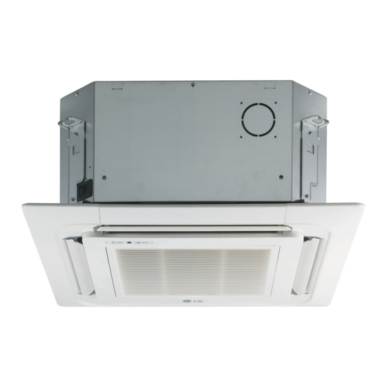
INSTALLATION MANUAL
AIR
CONDITIONER
Please read this installation manual completely before installing the product.
Installation work must be performed in accordance with the national wiring
standards by authorized personnel only.
Please retain this installation manual for future reference after reading it
thoroughly.
Multi Type
MFL68280103
Rev.04_122120
Copyright © 2015 - 2020 LG Electronics Inc. All Rights Reserved.
www.lghvac.com
www.lg.com
Advertisement
Table of Contents


Need help?
Do you have a question about the A8UW54GFA0 and is the answer not in the manual?
Questions and answers