Table of Contents
Advertisement
Quick Links
Advertisement
Table of Contents

Related Manuals for TECH ST-81


Summary of Contents for TECH ST-81
- Page 2 Declaration of Conformity no. 23/2007 TECH, a company with a seated in Andrychów (43-120) at ul. St. Batorego 14, declares with full responsibility that the thermal controller ST-28 (230V, 50Hz) produced by the company complies with the provisions of the Ordinance of the Minister of Economy, Labour and Social Policy (Dz U.03.49.414)
- Page 3 WARNING! Electric device! Before you take any steps aiming at powering the device (connecting wires, installation of the device etc.), make sure the controller is not connected to the mains. The installation should be conducted by a certified electrician. Prior to commissioning of the controller, the measurements of the grounding efficiency of the electric motors and a boiler as well as insulation measurements must be taken.
-
Page 4: Description
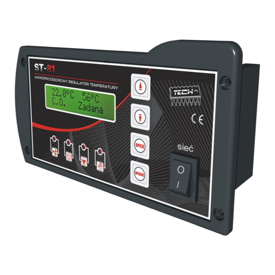
I. Description In order to check the flue gas outlet temperature, press EXIT (hold for several seconds) until the following screen is displayed: C.H. Screen H.C.W. Screen H.C.W. Screen Flue Gas Screen H.C.W. Screen C.H. Flue Fan Flue Gas Screen The left of the screen shows the boiler temperature;... -
Page 5: Controller Functionalities
A controller should be set up to meet individual requirements, depending on the type of fuel and a boiler. TECH shall bear no responsibility for the erroneous setup of the controller. II. Controller functionalities This section describes controller functions, settings and navigation issues. -
Page 6: B) Firing-Up
II.b) Firing-up The Firing-up functions switches the fan on or off during the continuous operation of the controller. If the boiler temperature exceeds 30 °C but does not reach the set value, the button is used as a START/STOP button and the LCD displays Fan On/Off message. - Page 7 The OPTIONS button enables/disables the hot water pump (of the boiler). The OPTIONS button enables/disables the alarm. II.d) The temperature of activation CH and UHW pumps. The option enables setup of CH pump and UHW pump activation temperatures (this refers to temperatures measured on the boiler).
-
Page 8: E) Hysteresis Of The Boiler
II.e) Hysteresis of the boiler This option allows setup of the set temperature hysteresis. This value represents a difference between the temperature of the temperature maintenance mode activation and the operation mode restoration temperature (e.g. if the set temperature is 60°C and the hysteresis value is 2°C, the temperature maintenance mode will be activated at 60°C, whereas the operation mode will be restored upon drop to 58°C. - Page 9 II.g) UHW pump Activation of UHW pump (by selecting TURN ON) makes the controller switch to boiler priority mode. In this mode, the boiler pump ( UHW) is activated until the set temperature is reached. Then, the pump is turned off and the CH circulating pump is activated.
-
Page 10: I) Summer Mode
II.i) Summer mode Upon activation of this function, this pump is deactivated and the UHW pump starts above the set temperature (see the pump activation temperature function), whereas the UHW pump operates continuously. The summer function allows to adjust only the boiler set temperature for heating the water in the vessel. -
Page 11: K) Default Settings
II. k) Default settings The controller comes with a default setup for operation. However, it should be customized to meet the individual needs. Default settings may be restored at any time. By selecting the default settings, all customized settings of boiler are deleted. This allows for setting new parameters of the boiler. -
Page 12: C) Temperature Protection
The blower is activated. The pump starts irrespective of the current temperature. The controller awaits for pressing the OPTIONS button. Next, the alarm is deactivated and the normal operation of the controller is restored. III.c) Temperature protection The controller has an auxiliary protection in case of damage to a bimetal sensor: upon exceeding the temperature of 85°C, the alarm is activated and the LCD displays: III. -
Page 13: E) Fuse
IV. Maintenance The technical conditions of the wires of the ST-28 controller should be inspected prior to the heating season as well as during its duration. The mounting of the controller should be checked and the dust and other contamination should be removed. -
Page 14: Technical Support
V. Technical support Any defects should be forwarded to the following address: TECH Sp.j. 34-120 Andrychów ul. St. Batorego 14 tel. 33 8705105 , 33 8759380 VI. Instllation WARNING: The installation should be conducted by a certified electrician! The device cannot be powered during theinstallation (make sure the plug is not connected to the means). -
Page 15: Table Of Contents
Contents I. Description...........................4 II. Controller functionalities....................5 II. a) Main screen......................5 II. b) Firing-up........................5 II. c) Manual operation....................6 II. d) The temperature of activation of CH and UHW pumps ......6 II. e) Hysteresis of the boiler..................7 II. f) Hysteresis of UHW....................8 II.
Need help?
Do you have a question about the ST-81 and is the answer not in the manual?
Questions and answers