Table of Contents
Advertisement
Quick Links
Advertisement
Table of Contents

Related Manuals for TECH ST-431


Summary of Contents for TECH ST-431
- Page 1 - 1 -...
- Page 2 ST-431 – user manual Declaration of Conformity No. 42/2010 Hereby, we declare under sole responsibility that the ST-431 230V 50Hz thermoregulator manufactured by TECH, ul. St. Batorego 14, 34-120 Andrychów, is compliant with the Regulation by the Ministry of Economy. (Journal of Laws Dz.U.
- Page 3 ATTENTION! High voltage! Make sure the regulator is disconnected from the mains before working on the power supply (cable connections, device installation, etc.)! All connection works must only be carried out by qualified electricians. Before activating the controller, measure the motor resetting efficiency and inspect wire insulation.
- Page 4 ST-431 – user manual - 4 -...
-
Page 5: Application
I. Application Thermoregulator type ST-431 is intended for operation of three- or four-way mixing valve with a possibility of connecting additional valve pump. Optionally, the controller may cooperate with two modules ST- 61, which enables to control altogether three mixing valves. The controller is equipped with weather control function,1-week program and may cooperate with the room regulator. -
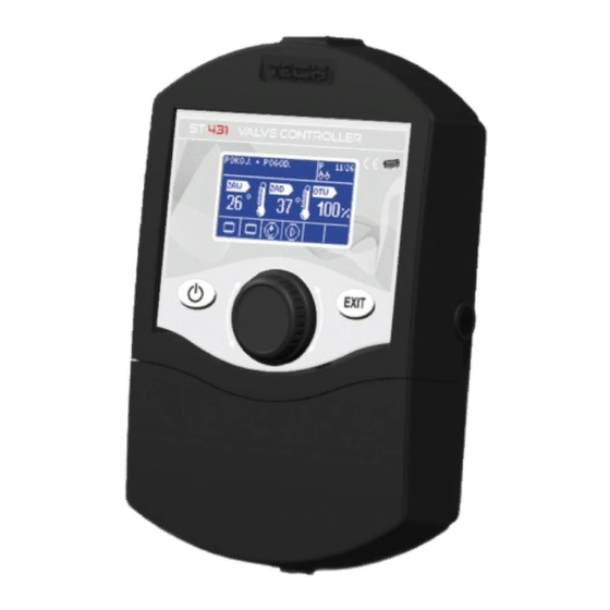
Page 6: A) Main Page
ST-431 – user manual circulation with the controller of the boiler, the pump should be connected from the boiler controller (pump outlet from regulator TS-431 will remain disconnected). The control takes place with the use of pulse generator knob. Entering the menu and confirming settings proceed by pressing the knob. -
Page 7: Main Menu
III. Main menu III.a) Set temperature With this option, the requested temperature the valve is supposed to maintain, is set. In the course of correct operation, the temperature of water behind the valve will be approaching the preset valve temperature. -
Page 8: E) Manual Operation
ST-431 – user manual Using this function, initial setting of the valve is controlled. During calibration, the valve is set to a safe position, that is, for CO valve, to a fully open position, while for floor valve - to a closed position. During calibration, at the bottom of the screen, the following symbol is displayed: III.e) Manual operation... -
Page 9: I) Factory Settings
III.i) Factory settings The regulator is pre-configured for operation. However, it should be adjusted for own needs. Return to the factory settings is possible at any moment. By activating the factory settings option, all own adjustments are replaced by the settings saved by the manufacturer. From that moment, the own parameters may be set once again. -
Page 10: C) Boiler Sensor
ST-431 – user manual IV.c) Boiler sensor In this submenu, the user determines basic boiler protection parameters and pump activation. IV.c.1) Return protection This function permits setting the boiler protection against too cool water returning from the main circulation, which could cause low-temperature boiler corrosion. -
Page 11: D) Temperature Control
ST-431. IV.d) Temperature control This parameter determines water temperature measurement (control) frequency behind the CH or HWT installation valve. If the sensor indicates a change in temperature (deviation from the set value), then the electric valve will open or close by the set stroke, in order to return to the preset temperature. -
Page 12: H) Maximum Floor Temperature
ST-431 – user manual Proportionality coefficient is used for defining valve stroke. The closer the preset temperature, the smaller the stroke. If this coefficient is high, the valve will faster achieve the opening close to the relevant. However, the opening will not be accurate. Single opening percentage is calculated on the... -
Page 13: K) Opening Time
(see chapter: IV.e). The reduced preset temperature will not be displayed on the main screen of the controller. The information that the room regulator indicated that the room is heated up is signalled by room regulator symbol<p>(continuous display, not pulsating). -
Page 14: N) Valve Type
ST-431 – user manual IV.m) Minimum opening The parameter determines, which valve opening may be the smallest Thanks to that parameter, the valve may be opened minimally, to maintain the smallest flow. IV.n) Valve type By means of this setting, the user selects the type of the controlled valve between: CH - it is set to adjust CH circulation temperature. -
Page 15: M) Minimum Opening
2. Temperature control This parameter determines the sampling (control) frequency of the water temperature behind the valve for the CH or the HUW system. If the sensor indicates a change in temperature (deviation from the set value), then the electric valve will open or close by the set stroke in order to return to the set temperature. -
Page 16: P) Valve 2
ST-431 – user manual sensors of the main controller. 10. Valve removal This function is used for a complete removal of the valve from the controller memory. Valve removal is used e.g. at disassembling the valve or module replacement (re-registration of a new module is necessary). -
Page 17: T) Weekly Control
0ºC and 10ºC. The more points constructing the curve, the greater its accuracy, which allows its flexible shaping. In our case, four points seem a very good compromise for large accuracy and for easiness of setting of the course of this curve. - Page 18 ST-431 – user manual In this mode, specific hours and the requested deviations from the preset temperature should be marked (by how many degrees the temperature is supposed to raise or drop in a given hour) for each day of the week.
-
Page 19: U) Timer
(the preset temperature), the digit with the value of the currently preset deviation shall be pulsating (informing at the same time about the weekly control activity). IV.u) Timer By setting the timer, a user defines the current time and weekday. Without setting the time, correct operation of the weekly control is not possible. -
Page 20: Maintenance
ST-431 – user manual V. Maintenance In controller TS-431, before the heating season and throughout its duration, technical condition of wires should be checked. Fastening of the controller should be also checked, it should be cleaned from dust and other dirt. - Page 21 Schematic diagram - 21 -...
-
Page 22: Table Of Contents
ST-431 – user manual Contents I. Application..................5 II. Principle of operation................5 II. a) Main page..................6 III. Main menu..................7 III. a) Set temperature................7 III. b) Activated..................7 III. c) Screen view................7 III. d) Valve calibration................7 III. e) Manual operation...............8 III. f) Installer menu................8 III. - Page 23 - 23 -...
- Page 24 - 24 -...
Need help?
Do you have a question about the ST-431 and is the answer not in the manual?
Questions and answers