Table of Contents
Advertisement
Quick Links
Thank you for purchasing this Koganei product. Please read this instruction manual carefully before using the device, so that you can use
it safely and correctly. In addition, keep this manual in a safe place.For product handling and precautions, refer to "Safety Precautions" and
"Handling Instructions and Precautions" in "Catalog No. A5046" before using.
1. Safety precautions
Expresses situations that can be clearly
predicted as dangerous. If the noted danger is
not avoided, it could result in death or serious
DANGER
injury.
It could also result in damage or destruction of
assets.
Expresses situations that, while not immediately
dangerous, could become dangerous. If the
noted danger is not avoided, it could result in
WARNING
death or serious injury.
It could also result in damage or destruction of
assets.
Expresses situations that, while not immediately
dangerous, could become dangerous. If the
noted danger is not avoided, it could result in
CAUTION
light or semi-serious injury.
It could also result in damage or destruction of
assets.
While there is little chance of injury, this content
ATTENTION
refers to points that should be observed for
appropriate use of the product.
1.1
Danger
● Do not use in locations where explosives, flammables, or other
dangerous substances are present. This product is not an
explosion-proof type unit. Explosion or ignition may occur.
● When any wiring, installation, or inspection work is to be
carried out, make sure that the unit is disconnected from the
power supply, otherwise, an accident, an electrical shock or a
malfunction may be caused.
● Never attempt to remodel the product. It could result in abnormal
operation leading to injury, electric shock, fire, etc.
● Do not splash water on the product. Spraying it with water,
washing it, or using it underwater could result in malfunction of
the product leading to injury, electric shock, fire, etc.
● If the equipment is used in a manner not specified by the
KOGANEI, the protection provided by the equipment may be
impaired.
1.2
Warning
● Do not use the product in excess of its specification range. Doing
so creates the risk of product breakdown, loss of function, or
damage. It could also drastically reduce the operating life.
● Because this product is used to detect objects, it does not have
control functions meant for accident prevention or for other safety
assurance purposes.
1.3
Attention
● When the product can no longer be used or is no longer
necessary, dispose of the consumables appropriately as industrial
waste.
● Do not touch the pressure sensor head when power supply is on.
Owner's Manual
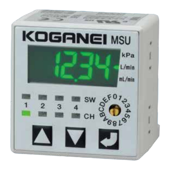
Multi-Channel, Multi-Sensor Controller [MSU]
2. Product overview
This product is a device that connects to and displays the values
from sensor devices that have pressure, flow rate, and a variable
1- to 5-volt DC output. It can also receive output from sensor
devices and control its output according to those values.
You can also select either the RS-232C communication type or
the RS-485 communication type, depending on your use and
purpose.
I f any sensors except our pressure sensors (MSU-PH- □ ) are
connected to the controller, UL authentication is limited to the
controller.
3. Contents of the product set
When you receive this product, before you use it, check
whether there are any missing items, and whether there were
any abnormalities or damages that occurred during shipping. If
there are damages, or if the product does not operate normally,
contact your retailer (agent) or our nearest sales office.
3.1 Contents in the package
・ The multi-channel, multi-sensor controller
・ Owner's Manual English
・ Owner's Manual Japanese
・ Other accessories, cables, mounting brackets, and panel
mounting parts are included according to the model.
- 1 -
M140821
Ver. 1.3
1
1
1
Advertisement
Table of Contents

Related Manuals for Koganei MSU-PH-EA Series


Summary of Contents for Koganei MSU-PH-EA Series
- Page 1 ● Do not splash water on the product. Spraying it with water, washing it, or using it underwater could result in malfunction of the product leading to injury, electric shock, fire, etc. ● If the equipment is used in a manner not specified by the KOGANEI, the protection provided by the equipment may be impaired. Warning ● Do not use the product in excess of its specification range. Doing so creates the risk of product breakdown, loss of function, or damage.
-
Page 2: Specifications
4. Specifications Item Specifications Operating -10 to 50℃; when stored: -20 to 80℃ temperature range (non-condensation, non-freezing) 4.1 List of controller specifications Operating humidity 35 to 85% RH range Item Specifications Dielectric strength 500 VAC for 1 minute 12 to 24 VDC ±10% *Use a Class 2 Insulation resistance 100 MΩ MIN (at 500VDC megger) Voltage power supply. Endurance: 10 to 55 Hz; secondary Sensor head supply 12 to 24 VDC ±10% (*Depending on Vibration resistance amplitude: 1.5 mm, 2 hours in each Power supply voltage power supply voltage) direction (XYZ) 100 mA MAX. (Not including supply General Endurance: 490 m/s Consumption current power to sensors) -
Page 3: Rs-485 Communication Specification
Pressure sensor head: Characteristic tables of pressure and output ●MSU-PH-EA-□ ●MSU-PH-ER-□ ●MSU-PH-EM-□ 4.64 3.75 10 20 30 40 50 60 70 80 90 101.3 −100 −50 −100 0 100 200 300 400 500 600 700 800 900 1000 Pressure (kPa) Pressure (kPa) Pressure (kPa) 5. - Page 4 5.2 Wiring specifications for the controller <MSU-□, MSU-232-□> <MSU-485-□> Wiring specifications Connector type Item Specifications Connector type Item Specifications 1 pin : 24V (red) Pin 1: 24 V (red) Power supply Power supply 2 pin : 0V (black) Pin 2: 0 V (black) 3 pin : SW1 (white) Pin 3: SW1 (white) Manufactured by JST B6B-XASK-1 4 pin : SW2 (green) Pin 4: SW2 (green) Switch Switch output output 5 pin : SW3 (yellow) Pin 5: SW3 (yellow) Made by JST 6 pin : SW4 (brown) Pin 6: SW4 (brown) B11B-XASK-1 Data input 7 pin : 0V (black) Pin 1: +V (brown) and output Pin 2: sensor output 8 pin : RXD (white) Manufactured by (black)
-
Page 5: Installation And Wiring
6. Installation and wiring Sensor head body Use the small screws provided to mount the sensor head. 6.1 Installation The tightening torque should not Sensor head and connector connection procedure exceed 6.0N・cm [0.53in・lbf]. When the sensor head MSU-PH-□-□ is supplied, the sensor head body and mini clamp connector (male) are not yet connected. Follow the procedure below to perform the connection. - Page 6 6.2 Wiring When connecting, refer to the figure below and use the provided power and signal cables. CAUTION ● In case noise generating equipment (switching regulator, inverter motor, etc.) is used in the vicinity of this sensor, connect the frame ground (F.G.) terminal of the equipment to an actual ground. Additionally, when selecting a power supply, choose one that is Class 2. ● Securely insert the connector. ● After completing wiring work, check to make sure that all connections are correct. ● Use a mechanical switch, photo coupler, or relay for external input. If the grounding potential of the external device to be used and the grounding potential of this product are different, the external device should have an insulated on/off procedure for the 0V line. ● Verify that the supply voltage variation is within the rating. Circuit Diagram 〈NPN output type〉 Separate type 4-channel controller Power/switch output cable Sensor head Channel 1ch (Red) (Brown)+V (Black)Vout:1 TO 5V Load (White) OUT1 (Blue) 0V Load Load (Green)...
- Page 7 7. Functions ■ Any sensor settings You can use a 1 to 5 V linear output sensor by setting the display value at 5 V and display value at 1 V. ■ External input Size correlations, as well as positive/negative, are irrelevant for Do assignments for functions (zero adjust or import reference) in display value at 5 V and display value at 1 V. settings (main unit operations or communications settings) when When using an optional sensor, do the various settings for the using external input (settings unused as factory default).
- Page 8 ■ Output mode settings Set the output mode for each channel. 0: Output OFF mode Always output OFF 1: Hysteresis mode Mode for setting the ON point and OFF point 2: Window comparator mode 1 (output cut when rising) Mode for turning output ON within the set value range for L1 and L2 (OFF point depends on response differential setting) Does not turn on when entering range while rising 3: W indow comparator mode Mode for turning output ON within the set value range for L1 and L2 (OFF point depends on response differential setting) 4: High mode Mode for turning output ON when above the ON point (OFF point depends on response differential setting) 5: Low mode Mode for turning output ON when below the ON point (OFF point depends on response differential setting) ■ Hysteresis Mode Positive pressure L2 (OFF lit) Negative pressure L1 (ON lit) Switch output When L1 > L2 When L1 < L2 L1(ON lit) L2(OFF lit)
- Page 9 ■ Window comparator mode 1 (mode that does not turn on when between L1 and L2 while rising) ・ M ode for freely setting L1 and L2. Note, however, that switch output does not go ON while flow rate is increasing. Hysteresis Switch output ■ Window comparator mode Hysteresis H1 Hysteresis H1 Hysteresis H2 Hysteresis H2 • To use Window Comparator Mode 1 and Window Comparator Mode, setting must be L1 > L2. ■ High Mode ■...
- Page 10 ■ Threshold value settings During hysteresis mode During window comparator mode High mode/Low mode L1: OFF point/ON point Threshold value upper limit ON point L2: ON point/OFF point Threshold value lower limit Unused ■ Import reference mode settings 0: import reference mode OFF 1: import reference mode ON ■ Reference Import Mode (in Hysteresis Mode) Positive Reference flow rate capture pressure ΔL L2 (OFF point) Negative pressure Reference pressure...
- Page 11 ■ Zero adjust settings ■ Input channel Calibrating the zero-point shifts the value of the display value Do settings to assign sensor input channels. when implemented to show zero. Set if output settings for 2 or more points via 1 input sensor are Do not do zero adjust when settings do not include a zero point in required. the other sensor settings (display 5000 at 5 V, display 1000 at 1 V, 1: IN1 etc.). 2: IN2 Settings can be done via the adjust retention settings for whether 3: IN3 or not zero adjust is retained at power OFF (factory default is set 4: IN4 to delete at power OFF). <Initial value> CH1: IN1 Settings for deleting or retaining calibrated values at power OFF CH2: IN2 Clear calibrated values CH3: IN3 0: delete CH4: IN4 1: retain ■ Hold settings ■ Backlight settings Do hold settings for display values.
- Page 12 <Error display> … Out of sensor voltage range (Displayed when 5.1 V or higher.) … Out of sensor voltage range (Displayed when 0.9 V or lower.) … Sensor heard disconnect (Displayed when 0.2 V or lower.) Sensor voltages between 0.9 and 1.0 V display the value 1.0 V. Sensor voltages between 5.0 and 5.1 V display the value 5.0 V. Display Meaning Required action Release by pressing and holding the button for more than 1 second.
- Page 13 <Settings mode> Setting Mode Selection △▽ … For checking the version and initializing to factory default Information settings. [Measuring Mode] △▽ … * * * * Sensor For selecting a sensor head, configuring the settings of any sensor, and specifying the sensor input channel. △▽...
- Page 14 1. Sensor Sensor head selection and configuration of the settings of any sensor. Setting channel selection Sensor head selection ■■■■ ■■■■ CH Setting channel lights CH Setting channel lights [Sensor] button button button button Returns to: • After the sensor head setting is changed, the threshold value is ※ [1. SEn] initialized to: Threshold Value = (Upper Limit Value + Lower Selects a sensor head.
- Page 15 2. Output Output mode setting, reference import mode setting, output inversion setting Setting channel selection Output mode selection ■■■■ ■■■■ CH Setting channel lights CH Setting channel lights [Output] button button button button ※ Returns to: Selects an output mode. CH1: Channel 1 oFF: OFF Mode Hys: Hysteresis Mode...
- Page 16 3. Threshold Threshold (L1, L2) setting, hysteresis (H1, H2) setting, and reference import ΔL setting configuration, and checking of the threshold value for the reference import mode Setting channel selection Setting value input ■■■■ ■■■■ CH Setting channel lights CH Setting channel lights [L1] button button button button ※※※ ※ Returns to: Configures the L1 CH1: Channel 1 [Allowable Input Range] threshold value setting.
- Page 17 4. Response Switch output ON delay setting, filter setting Setting channel selection Switch output ON delay setting selection ■■■■ ■■■■ CH Setting channel lights CH Setting channel lights [On Delay] button button button button ※ Returns to: Configures switch output CH1: Channel 1 oFF: Switch output ON, delay OFF ...
-
Page 18: External Input
6. External Input External input function assignment Setting channel selection External input function assignment selection ■■■■ ■■■■ CH Setting channel lights ■■■■ button button button ※ Returns to: CH1: Channel 1 oFF: External input not used CH2: Channel 2 rEF: Reference import execution CH3: Channel 3 Adj:Zero adjustment execution CH4: Channel 4... -
Page 19: Serial Communication
9. Serial Communication • Serial communication settings can be configured only for a type that has a communication function. Communication speed setting, communication compatibility settings (RS-232 Type only) Communication speed setting selection ■■■■ [Communication Speed] ■■■■ button button button Configures the [RS-232 Type] [RS-485 Type] 9.6: 9600 bps communication 9.6: 9600 bps speed setting. 19.2: 19200 bps 19.2: 19200 bps 38.4: 38400 bps 57.6: 57600 bps 115.2: 115200 bps Select using △ or ▽. -
Page 20: Troubleshooting
When sending commands in succession, send the next command after receiving a response from the command you sent. For information on communications settings for PLC, computers, etc., refer to the user's manual for the device or software you are using. Each setting of a type that has a communication function can also be done with support software.Please download the support software from our website. 10. Troubleshooting If product operation appears to be abnormal, immediately shut off the power to the main unit, disconnect the connection cable from the main unit’s power connection terminal, and check the items in this section. If the abnormal situation continues, it may mean that a breakdown has occurred. Contact the outlet (the agency) at which you purchased the product, or the nearest Koganei service station. JUST CONSULT US: KOGANEI CORPORATION OVERSEAS DEPARTMENT 3-11-28, Midoricho, Koganei-shi, Tokyo, 184-8533, Japan TEL:+81- 042-383-7271 FAX:+81- 042-383-7276 Website: http://www.koganei.co.jp The specifications or the appearance of this product are subject to change any time without prior notice.
Need help?
Do you have a question about the MSU-PH-EA Series and is the answer not in the manual?
Questions and answers