Table of Contents
Advertisement
Quick Links
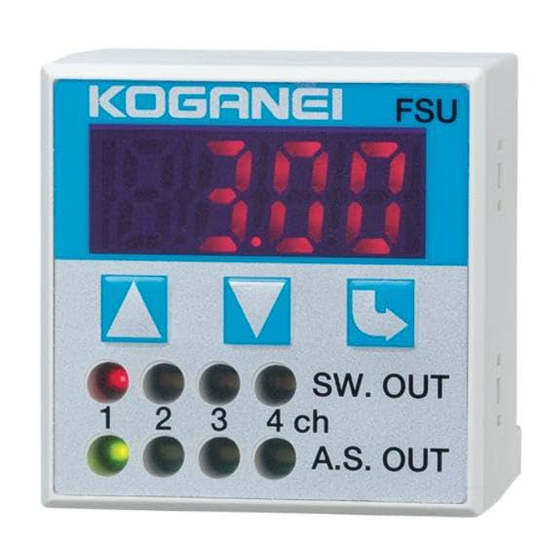
Multi-channel Flow
Rate Sensor Controllers
The Flow rate sensor detects workpieces lifted by vacuum
that could not be detected by the pressure sensor.
A single controller detects four points at the same time
Connectable to a personal computer
● Use a PC to perform flow rate setting, capture of flow rate
value, and reference flow rate setting.
PSU
S.W.OUT
1
2
3
4
ch
A. S. OUT
Three types of sensor heads, depending on flow rate range
● Three types are available,
including
–500〜500 mR/min (ANR),
[–30.5〜30.5 in.
3
/min.]
–3〜3R/min (ANR),
[–0.11〜0.11 ft.
3
/min.]
and 0〜10R/min (ANR),
.
[0〜0.35 ft.
3
/min.]
Not affected by piping resistance
● Since the flow rate sensor head is not affected by piping
resistance, there is no restriction on mounting position.
Measurement
point 1
Nozzle hole
diameter
100 mm
0.1 mm [0.004 in.]
[3.94 in.]
Measurement results using
φ1.8 [0.071 in.] tube
Measurement point 1
Flow rate sensor
0.11R/min [0.0039 ft.
Pressure sensor
−78 kPa [−11.3 psi.]
※ Based on Koganei test standard.
799
PSU
S.W.OUT
1
2
3
4
ch
A. S. OUT
RS232C
Measurement
Vacuum
point 2
source
−98 kPa
[−14.2 psi.]
2000 mm [78.7 in.]
100 mm
[3.94 in.]
Measurement point 2
3
/min.]
0.12R/min [0.0042 ft.
3
/min.]
−95 kPa [−13.8 psi.]
Output Mode
■ Window comparator mode 1
・Mode for freely setting L1
and L2.
Note, however, that switch
output does not go ON while
flow rate is increasing.
L (R/min)
L1
L2
Switch
output
■ Window comparator mode 2 and 3
• Modes for automatically
setting L1, using ΔL setting
and reference flow rate
capture. (L1= Reference
flow rate −ΔL)
L (R/min)
L2
Switch
output
●Window comparator mode 2
• When L1 has been set, this mode maintains it unchanged until reference
flow rate capture is performed again.
●Window comparator mode 3
• Each time the L1 setting is deleted when switch output goes OFF, this
mode performs reference flow rate capture and sets L1.
Effective for situations where flow rate fluctuation is severe.
When using window comparator mode 3, use RS232C to perform
reference flow rate capture from outside.
■ Window comparator mode 4
• Mode for freely setting L1 and
L2.
L (R/min)
L1
L2
Switch
output
Discharge to
Vacuum
Workpiece
Vacuum
atmospheric
valve ON
lifted by
break
pressure
vacuum
ON
Discharge to
Vacuum
Workpiece
Vacuum
atmospheric
valve ON
lifted by
break
pressure
vacuum
Reference flow rate capture
ΔL
L1
ON
Discharge to
Vacuum
Workpiece
Vacuum
atmospheric
valve ON
lifted by
break
pressure
vacuum
ON
Hysteresis
t
Hysteresis
t
Hysteresis
Hysteresis
t
Advertisement
Table of Contents

Related Manuals for Koganei Flow FSU


Summary of Contents for Koganei Flow FSU
- Page 1 Measurement point 1 Measurement point 2 Flow rate sensor 0.11R/min [0.0039 ft. /min.] 0.12R/min [0.0042 ft. /min.] Pressure sensor −78 kPa [−11.3 psi.] −95 kPa [−13.8 psi.] L (R/min) ※ Based on Koganei test standard. Hysteresis Hysteresis Switch output...
-
Page 2: General Precautions
Safety Precautions (Multi-channel Flow Rate Sensor Controllers) Handling Instructions and Precautions DANGER ● While the product is in operation, do not attempt to adjust the General precautions attached mechanisms (connecting and disconnecting the wiring connector, or attach or position the sensor head, etc.). Wiring Abnormal operations could result in injury. -
Page 3: Mounting And Wiring
Handling Instructions and Precautions 7. On the sensor head body, connect the sensor head-side connector. Open the sensor head cover, connect the connector, and then close the cover. Cover Mounting and wiring Sensor head and connector connection procedure Sensor head-side connector When the sensor head FSU-□-□... -
Page 4: Setting Procedure
Setting procedure Caution 1. Since miswiring in the sensor head, or in the power supply, switch, and communication cable, can damage both the controller and sensor head, always check the wiring before switching on the power. 2. The setting conditions are written to EEPROM and saved. Be aware that EEPROM has a finite lifetime, with guaranteed number of times up to 100,000 times. -
Page 5: Detection Mode
Setting Procedure ■ Setting ● Reference flow rate capture method in window comparator mode 2 and 3 Detection mode Device key operation method For the operations method, see p.804 • Switching on the power supply (DC24V RS232C method For RS232C commands, see p.806 voltage) automatically provides detection mode. - Page 6 Hysteresis setting Flow rate display switch-off Use the following procedure to change the hysteresis for each Use the following procedure to switch off the flow rate display. channel. Procedure Device operation 7-seg display Remark Procedure Device operation 7-seg display Remark (Push both at 7-seg LED off (Push both at...
-
Page 7: Error Display
Setting procedure Zero point correction (Zero reset) Use the following procedure to perform zero point correction for each channel. Procedure Device operation 7-seg display Remark (Push both at to select channel the same time) Zero point correction Note: Zero point is cancelled when the power supply is switched OFF. - Page 8 Communication Communication with personal computer ● Communication command detail ● Hardware and operations environment PC: PC-98 series (excluding Command List Note: “ ” denotes a space. ﹈ PC-98LT) or equivalent DOS/V machine Function: Reads out the current flow OS: Windows95 or later rate value (1ch-4ch).
- Page 9 Communication Function: In output mode, the reference flow rate Function: Performs zero correction for each channel. capture when comparator modes 2 and 3 Send example: @B1 c/rl/f are selected. Response example: OK c/rl/f Send example: @P c/rl/f Response example: NG c/rl/f Response example: OK c/rl/f 21: illegal type 1:1CH...
- Page 10 For sending @A Function: Displays L1 = Reference flow rate−ΔL, and ※ c/rl/f : Enter key L2 for each channel. @A c/rl/f Sent Send example: @E1 c/rl/f ←L1 = Reference flow rate−ΔL Response example: 1.00 c/rl/f ←L2 0.50 c/rl/f Received c/rl/f 2ms MAX.
- Page 11 Communication ● Hyperterminal setting method Click File, and then click Clicking on the tag of the Settings in Figure 1 displays Property to open the window at Figure 3. Click the ASCII Connect To left, and set Setup... button. Configure... Click on Figure 1 Figure 3...
- Page 12 MULTI-CHANNEL FLOW RATE SENSOR CONTROLLERS Specifications ● Multi-channel flow rate sensor controller Model Item Voltage DC24V±10% Power Note 1 Sensor head supply voltage DC24V±10% supply Consumption current 100 mA MAX. (Not including current supplied to sensors) Rated flow rate ・−500〜500 mR /min [−30.5〜30.5 in. /min.] (ANR) type Compatible sensor heads ・−3〜3R /min [−0.11〜0.11 ft.
- Page 13 Specifications ● Flow rate sensor heads Model FS-R3 FS-R05 FS-10 Item Gases targeted for Air/nitrogen. However, the detection media cannot contain chlorine, sulfur, acid, or other corrosive substances. Gas must also be dry. measurement Gas must be clean gas devoid of dust and mist (oil mist). −3〜+3R /min [−0.11〜0.11 ft.
-
Page 14: Order Codes
Flow Rate Sensor Head Flow Rate and Output Characteristics Graphs ● FS-R05 ● FS-R3 ● FS-10 Flow rate and output characteristics Flow rate and output characteristics Flow rate and output characteristics −500 −400 −300 −200 −100 100 200 300 400 500 −3.0−2.5−2.0−1.5−1.0−0.5 0.0 0.5 1.0 1.5 2.0 2.5 3.0 0.0 1.0 2.0 3.0 4.0 5.0 6.0 7.0 8.0 9.0 10.0 m R /min (ANR)... - Page 15 Dimensions mm [in.] ● FSU-S-□ Wiring label enlarged view 2 1 3 4 c c c c SENSOR 1 : +V 2 : 1−5V 11 10 3 : 0V 4 : PIN 0 0 4-digit LED flow rate indicator Wiring label Mode button 40 [1.575] 35.4 [1.394] The connector for 4-sensor head 27.6 [1.087] [0.307]...
- Page 16 Dimensions mm [in.] ● PSUW-□-□ ● PSU-BR 2- φ4.5 [0.177] (L) (50 [1.97]) [0.374] Power and switch output cable (6 leads) 11 16 [0.433] [0.630] [0.276] (7 [0.276]) 24 Model 2- φ2.9 [0.114] [0.945] PSUW- □ 3000 [118] PSUW- □ 5000 [197] 30 [1.181] 4 ...
- Page 17 Special Products ●Vacuum Valve Unit with flow rate sensor CRCB-0064W Adjusting needle for vacuum breaking flow Flow rate sensor head P: Pressure port R: Exhaust port VS: Vacuum supply port V: Vacuum port ●Micro ejector with flow rate sensor CRCB-0065W Adjusting needle for vacuum breaking flow P: Pressure port R: Exhaust port Flow rate sensor head V: Vacuum port Note: For detailed specification and dimension, consult us.
Need help?
Do you have a question about the Flow FSU and is the answer not in the manual?
Questions and answers