
Related Manuals for ETC PENKO 1020 FMD


Summary of Contents for ETC PENKO 1020 FMD
- Page 1 1020 FMD PENKO Engineering B.V. Your Partner for Fully Engineered Factory Solutions Quick Start: 1020 FMD...
-
Page 2: Table Of Contents
1020 FMD Table of Contents Introduction ............................3 In the box ............................3 Needed for use ..........................3 Overview ........................... 4 Connections ..........................5 Power supply ........................5 Load cell ..........................6 Display and keypad ........................7 First use ........................... 11 Standard factory settings ...................... -
Page 3: Introduction
1020 FMD Introduction The PENKO 1020 FMD is a compact comprehensive Force Measurement Device. In the box The box contains the following items: 1 x 10²⁰ FMD device 1 x rubber ring for mounting purpose 2 x clip for mounting purpose ... -
Page 4: Overview
1020 FMD 1 Overview Option 1: Option 2:... -
Page 5: Connections
1020 FMD Number Description TFT display 320 x 240 Keypad OPTION: None || Serial + CAN bus || Profibus Ethernet connection USB connection Digital inputs (3) Digital outputs (4) 24VDC power supply OPTION: Analog output Load cell connection RS232/RS422 connection CAN bus connection Profibus connection Bus termination for Profibus... -
Page 6: Load Cell
1020 FMD 2.2 Load cell Property Description Wiring With sense Type of sense Passive Excitation voltage 5 VDC Sensitivity 0,1 μV/d Selectable ranges 1 mV/V | 1,5 mV/V | 2 mV/V | 2,5 mV/V | 3 mV/V Input voltage @3mV/V -16 mV to 16 mV A/D Conversion speed 1600/s... -
Page 7: Display And Keypad
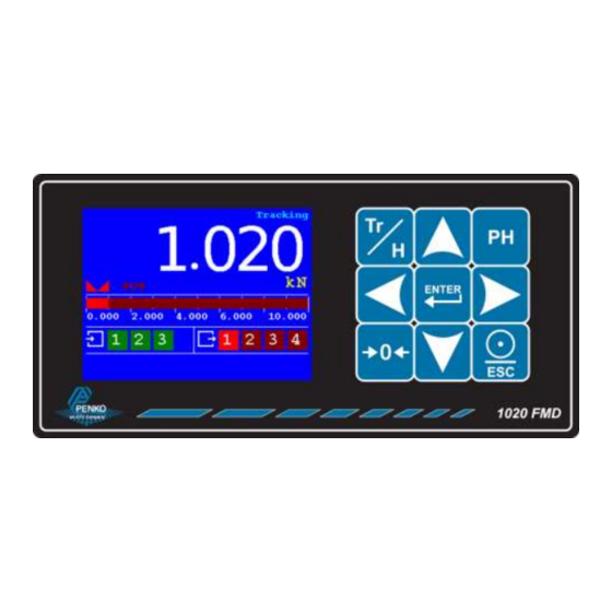
1020 FMD 3 Display and keypad The display contains the following indications: Number Description Indicator in stable range [] Zero active [] Range/Interval active Bar graph indication Digital input active indication (3 inputs) Digital output active indication (4 outputs) Measured value Type of value shown on the display (Tracking, Hold, T.I.R, Peak, Valley) * * Display value Tracking... - Page 8 1020 FMD Hold function Peak, Valley and T.I.R. function...
- Page 9 1020 FMD The display indications in menu mode: Number Description Active buttons for current menu item TAC and CAL code* Menu level * TAC and CAL code TAC stands for Traceable Access Code. A number of settings are only available after entering this code.
- Page 10 1020 FMD The keys have the following functions: Tracking / Hold Toggle between Tracking mode and Hold mode. Peak Hold Show Peak Hold mode. Enter / Menu Adjust levels. Press > 2 seconds to enter configuration menu. In menu mode, press to confirm setting.
-
Page 11: First Use
1020 FMD 4 First use For first use, the following settings are important: Unit indication Decimal point position Step size Maximum load Calibration This chapter describes how to adjust these settings. Main Menu From the main screen, press the Enter button for 2 seconds to enter the Main Menu. Press 2 seconds... - Page 12 1020 FMD Navigate through menu Use the Up and Down button to navigate through the menus. Use the Enter button to enter a menu item. Use the Escape button to step back a level. Down Open menu Back to item previous level Edit a value Use the arrow buttons to edit a value.
- Page 13 1020 FMD Edit a text In case a text has to be edited, a keyboard appears on the screen. Use the arrow buttons to navigate through the keyboard. Use the Enter button to select the character. Use the Zero button for backspace. Use the Peak-hold button to change the character set.
- Page 14 1020 FMD Indicator parameters The indicator parameters can be set as follows: Enter the TAC as shown on the right bottom corner of the screen using the arrow buttons - apply with the Enter button...
- Page 15 1020 FMD Here the Unit, Step size, Decimal point and Max load can be set Unit Set the unit of measurement, for example kN or N. This will be shown everywhere the measured force is displayed or printed. Decimal point Select the position of the decimal point.
- Page 16 1020 FMD Available options Example: Measured value is 2005 kN. Step size Displayed value 2005 2006 2005 2010 2000 2000 2000 2000 Maxload Set the force the indicator will use as maximum. If the measured force is higher than the maximum load, the display will show ======...
- Page 17 1020 FMD Calibration Enter the CAL as shown on the right bottom corner of the screen using the arrow buttons - apply with the Enter button...
- Page 18 1020 FMD Make sure the load cell or force sensor is not loaded and is stable before pressing Enter Make sure the load cell or force sensor is loaded with the reference weight and is stable before pressing Enter...
- Page 19 1020 FMD Enter the reference weight - apply with the Enter button The device is now calibrated Error codes: Error code Description Solution CCCCCC No proper calibration available Check calibration setting UUUUUU Underflow Check load cell Check platform construction OOOOOO Overflow Check load cell Check platform construction...
-
Page 20: Standard Factory Settings
1020 FMD 5 Standard factory settings Description Display Value Your setting Properties Name … Unit label Step Decimal point 0,000 Max Load 10,009 kN Sample Rate 1600/s Stable condition Range 0,002 kN Time 1,00 s Zero tracking Range 0,000 kN Step 0,000 kN Time... -
Page 21: Menu Structure
1020 FMD 6 Menu structure... - Page 22 1020 FMD...
- Page 23 1020 FMD...
- Page 24 A complete overview you will find on: www.penko.com/dealers PENKO Engineering B.V. ▪ Schutterweg 35, NL 6718XC Ede ▪ Tel +31 (0) 318525630 ▪ Fax +31 (0) 31852971 ▪ info@penko.com Web ▪ www.penko.com ▪ 7600M1063 ▪ Copyright © 2014 ETC All rights reserved.