
Related Manuals for ACV Comfort ME 200


Summary of Contents for ACV Comfort ME 200
- Page 1 Comfort ME 200 - 300 Installation, Operation & Maintenance Instructions for the User and the Installer A1007845 - 661Y3200 • C...
-
Page 2: Table Of Contents
Energy labelling ..............................5 Rating Plate ................................6 APPLIANCE DESCRIPTION ................7 TECHNICAL CHARACTERISTICS ...............8 Main characteristics : Comfort ME 200 - 300 ................8 Dimensions : Comfort ME 200 - 300 ....................9 Heating connections ............................10 Domestic hot water connections ...................... - Page 3 Table of Contents STARTING UP ...................25 Safety instructions to fill the tank ......................25 Filling ....................................26 Checks before starting up .........................28 Starting up .................................28 MAINTENANCE ..................29 Periodic checks by the user ........................29 Annual maintenance ............................29 Draining ..................................30 Bringing back into service after maintenance ................30 Fault finding ................................32...
-
Page 4: General Recommendations
• The part number (P/N) and serial number (S/N) of the appliance are indicated on its rating plate and must be provided to ACV in case of warranty claim. Failure to do so will make the claim void. •... -
Page 5: Product Information
Product Information ENERGY LABELLING Comfort ME: A1007845 - 661Y3200 • C... -
Page 6: Rating Plate
Product Information RATING PLATE Comfort ME: A1007845 - 661Y3200 • C... -
Page 7: Appliance Description
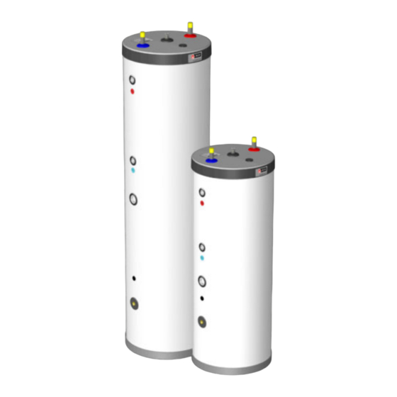
Appliance Description MODELS - Comfort ME 200 - 300 High efficiency storage water tanks, multi-energy type, to be installed on the floor. Possibility to heat by coil, by heat transfer fluid or by optional electrical resistance. 1. Cold water inlet 9. -
Page 8: Technical Characteristics
Technical Characteristics MAIN CHARACTERISTICS : COMFORT ME 200 - 300 Comfort ME Main characteristics Total capacity Primary circuit capacity (heating) DHW circuit capacity Coil capacity Primary pressure drop* mbar 22.4 23.5 Coil pressure drop mbar Tank heating surface m² 1.03 1.26... -
Page 9: Dimensions : Comfort Me 200 - 300
Technical Characteristics DIMENSIONS : COMFORT ME 200 - 300 Comfort ME 200 360 mm Ø 529.3 mm Comfort ME 300 Comfort ME: A1007845 - 661Y3200 • C... -
Page 10: Heating Connections
Dimensions of connections Models Heating Coil Optional electrical connection connection heating element connection Comfort ME 200 Ø 1" [F] Ø 1" [M] Ø 1"½ [F] Comfort ME 300 Ø 1" [F] Ø 1" [M] Ø 1"½ [F] After-heating flow connection... -
Page 11: Domestic Hot Water Connections
Technical Characteristics DOMESTIC HOT WATER CONNECTIONS Dimensions of connections Models Cold / hot water connections Comfort ME 200 Ø 3/4" [M] Comfort ME 300 Ø 3/4" [M] Cold water inlet connection DHW dry well Domestic hot water outlet connection MAXIMUM OPERATING CONDITIONS Comfort ME Max. -
Page 12: Domestic Hot Water Performances
Technical Characteristics DOMESTIC HOT WATER PERFORMANCES Comfort DHW performance : Heating source = Coil * L/10' 45°C [∆T = 35K] Peak flow at L/10' 60°C [∆T = 50K] 45°C [∆T = 35K] Constant flow at 60°C [∆T = 50K] L/60' 45°C [∆T = 35K] Peak flow 1 hour at... -
Page 13: G3 Requirements And Guidance - Uk Only
Technical Characteristics G3 REQUIREMENTS AND GUIDANCE Discharge pipe from safety valves The Building Regulation G3 requires that any discharge from an unvented system is con- veyed to where it is visible, but will not cause danger to persons in or about the building. The tundish and discharge pipes should be fi tted in accordance with the requirements and guidance notes of Building Regulation G3. - Page 14 Technical Characteristics 3.55 Any discharge should be visible at the tundish. In addition, where discharges from safety devices may not be apparent, e.g. in dwellings occupied by people with impai- red vision or mobility, consideration should be given to the installation of a suitable safety device to warn when discharge takes place, e.g.
- Page 15 Technical Characteristics cage or similar guard is positioned to prevent contact, whilst maintaining visibility; (d) discharges at high level: e.g. into a metal hopper and metal downpipe with the end of the discharge pipe clearly visible or onto a roof capable of withstanding high temperature discharges of water and 3m from any plastic guttering system that would temperature relief valve to tundish collect such discharges.
- Page 16 Technical Characteristics Worked example of discharge pipe sizing Figure on the left shows a G1/2 temperature relief valve with a discharge pipe (D2) having 4 No. elbows and length of 7m from the tundish to the point of discharge. From Table: Maximum resistance allowed for a straight length of 22mm copper discharge pipe (D2) from a G1/2 temperature relief valve is 9.0m.
-
Page 17: Electrical Characteristics
POSITION OF DHW SENSOR Optional heating element The models Comfort ME 200 - 300 can be installed with a self-controlled heating element with built-in control safety thermostats. The control thermostat of the tank cannot control the heating element. To be mounted with an external box with a switch and a circuit breaker - not included in the delivery. -
Page 18: Installation
Installation PACKAGE CONTENTS The Comfort ME 200 - 300 appliances are delivered assembled, tested and packed. At product reception and after removal of packaging, check the package contents and that the appliance is free of damages. Contents packaging : •... -
Page 19: Safety Instructions
Installation SAFETY INSTRUCTIONS General remarks • Connections (electrical, hydraulic) must be carried out in accordance with applicable standards and regulations. • If the water drawing off point is far from the tank, installing an auxiliary DHW loop can allow to get hot water more quickly at all times. Essential instructions for the correct operation of the system •... - Page 20 The upper hot water layer may then reach very high temperatures. • ACV recommends using a pre-set thermostatic mixing valve in order to provide hot water at a maximum of 60°C. • Water heated to wash clothes, dishes and for other uses can cause serious burns.
-
Page 21: Connection
• Hot water can burn! ACV recommends using a pre- set thermostatic mixing valve in order to provide hot water at a maximum of 60°C. Essential instructions for the correct operation of the system •... -
Page 22: Connection To The Dhw Circuit (Typical Floor Installation)
Installation CONNECTION TO THE DHW CIRCUIT (Typical floor installation) 1. Filling valve 2. Pressure reducing valve (set at 4.5 bar) 3. Check valve 4. Expansion vessel 5. Safety valve (set at 7 bar) 6. Drain valve 7. Hot water outlet 8. -
Page 23: Example Of Standard Installation
Installation EXAMPLE OF STANDARD INSTALLATION Comfort ME combined with a boiler and solar panels. Comfort ME: A1007845 - 661Y3200 • C... -
Page 24: Comfort Me Tank Used As Electric Dhw Tank Only
Installation COMFORT ME TANK USED AS ELECTRIC DHW TANK ONLY Do not power the heating element if the primary tank is not filled and bled of air. System filling valve 2. Safety valve set to 3 bar 3. Expansion vessel 4. -
Page 25: Starting Up
Starting Up SAFETY INSTRUCTIONS TO FILL THE TANK Essential instructions for the safety of persons and the environment • The DHW tank must always be filled and pressurised before filling and pressurising the primary circuit. • Do not use vehicle antifreeze. This can cause serious injury or death, or damage facilities. -
Page 26: Filling
Starting Up FILLING Essential instruction for the correct operation of the system • The DHW tank must always be filled and pressurised before filling and pressurising the primary circuit. FILLING THE DHW TANK (Figure 1) General remark • Connect the safety valve outlet to the sewer. To fill the tank, open a hot water tap (2) located at the highest point of the system. - Page 27 Starting Up Figure 1 Cold water Hot water Figure 2 Figure 2 Comfort ME: A1007845 - 661Y3200 • C...
-
Page 28: Checks Before Starting Up
Starting Up CHECKS BEFORE STARTING UP • Check that the safety valves (DHW and primary) are correctly installed and that the out- lets are connected to the sewer. • Check that the DHW tank and the primary circuit are filled with water. •... -
Page 29: Maintenance
Maintenance PERIODIC CHECKS BY THE USER • Check the pressure of the primary circuit pressure gauge: it should be between 0.5 and 1.5 bar. • Visually inspect, on a regular basis, the valves, connections and accessories in order to detect any leaks or malfunction. •... -
Page 30: Draining
Maintenance DRAINING Essential instruction for the safety of persons and the environment • The water coming out of the drain valve is very hot and can cause very severe burns. Make sure the area around the hot water flow is clear of people. Essential instruction for the electrical safety •... - Page 31 Maintenance Figure 3 Cold water Hot water Figure 4 Comfort ME: A1007845 - 661Y3200 • C...
-
Page 32: Fault Finding
Check the electric heating element and replace if necessary. Models Comfort ME 200 - 300 Comfort ME 200 - 300 + electric heating element Comfort ME 200 + 300 + control thermostat kit Comfort ME: A1007845 - 661Y3200 • C... - Page 33 Comfort ME: A1007845 - 661Y3200 • C...
- Page 34 Comfort ME: A1007845 - 661Y3200 • C...
- Page 35 Comfort ME: A1007845 - 661Y3200 • C...
Need help?
Do you have a question about the Comfort ME 200 and is the answer not in the manual?
Questions and answers