Advertisement
Available languages
Available languages
Quick Links
Advertisement

Related Manuals for RTW DigitalMonitor 10500X-PLUS


Summary of Contents for RTW DigitalMonitor 10500X-PLUS
- Page 1 Bedienungsanleitung/Operating Manual...
- Page 2 © 50765 50746 Hinweis: Note:...
- Page 3 Inhaltsverzeichnis/Table of Contents Bedienungsanleitung deutsch ......9...
- Page 4 D 5.2.3.1. Routing, Label, Color ................79 D 5.2.3.2. Dig-Errors ....................81 D 5.2.5.1. Routing, Label, Color ................85 D 5.2.5.2. Dig-Errors ....................87 D 5.2.5.3. BS.1771 Mix Select ................88 D 5.2.7.1. more .. für Primary Function: SSA ............91 D 5.2.7.2.
- Page 5 Operating Manual english ......131 Toggle function ....................152 Instrument functions and button/key captions ............152...
- Page 6 E 5.2.3.1 Routing, Label, Color ................199 E 5.2.3.2 Dig-Errors .................... 201 E 5.2.5.1. Routing, Label, Color ................205 E 5.2.5.2. Dig-Errors ................... 207 E 5.2.5.3. BS.1771 Mix Select ................208 E 5.2.7.1 more .. for Primary Function: SSA ............211 E 5.2.7.2 more ..
-
Page 9: Bedienungsanleitung Deutsch
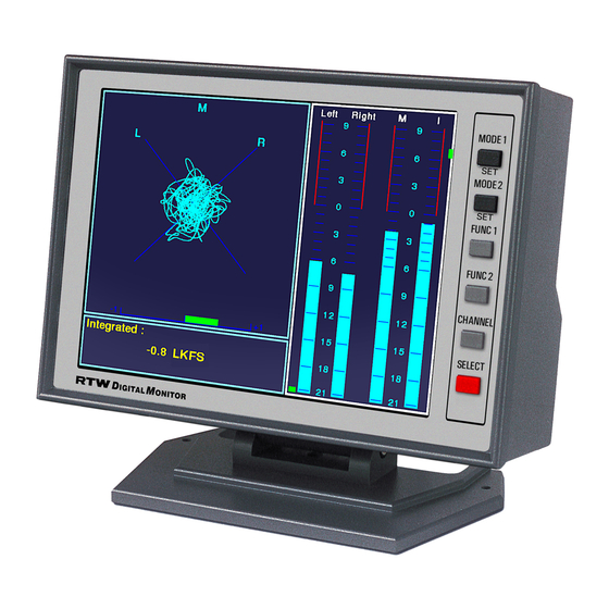
Bedienungsanleitung deutsch... - Page 11 D 1. Bevor Sie beginnen Bild D 1-1: DigitalMonitor 10500X-PLUS...
- Page 12 ©...
- Page 17 D 2. Funktionsübersicht Multi Instrument 1: Program Meter Multi Instrument 1 Program Meter Multi Instrument 2 Multi Instrument 2: Bild D 2-1: Die Displayelemente des DigitalMonitor 10500X-PLUS...
- Page 18 © Bild D 2-2: Die Peak-Program-Meter-Anzeige (rechts), hervorgehoben mit wei- ßem Rahmen,...
- Page 19 Bild D 2-3: Die ITU BS.1771-Loudness-Meter-Anzeige (rechts), hervorgehoben mit weißem Rahmen,...
- Page 20 © Bild D 2-4: Das Multi Instrument 1 (links oben), hervorgehoben mit weißem Rah- men, zeigt den Stereo-Sound-Analyzer...
- Page 21 Bild D 2-5: Bildschirmfüllende Darstellung des Stereo-Sound Analyzer ohne Pro- gram Meter und ohne Multi-Instrument 2...
- Page 22 Bild D 2-6: Das Multi Instrument 1 (links oben), hervorgehoben mit weißem Rah- men, zeigt das Audio-Vektorskop (Lissajous) Bild D 2-7: Bildschirmfüllende Darstellung des Audio-Vektorskops ohne Program Meter und ohne Multi-Instrument 2...
- Page 23 Bild D 2-8: Das Multi Instrument 1 (links oben), hervorgehoben mit weißem Rah- men, zeigt den RTA Bild D 2-9: Bildschirmfüllende Darstellung des Spektrumanalysators (RTA) ohne Program Meter und ohne Multi-Instrument 2...
- Page 24 Bild D 2-10: Das Multi Instrument 1 (links oben), hervorgehoben mit weißem Rahmen, zeigt den Stereo-Correlator Bild D 2-11: Bildschirmfüllende Darstellung des Stereo-Correlators ohne Pro- gram Meter und ohne Multi-Instrument 2...
- Page 25 Bild D 2-12: Das Multi Instrument 1 (links oben), hervorgehoben mit weißem Rah- men, zeigt den Kanal-Status (AES Channel Status) Bild D 2-13: Bildschirmfüllende Darstellung der Channel-Statusanzeige ohne Program Meter und ohne Multi-Instrument 2...
- Page 26 © Bild D 2-14: Das Multi Instrument 2 (links unten), hervorgehoben mit weißem Rahmen, zeigt den AES-Status...
- Page 27 Bild D 2-15: Das Multi Instrument 2 (links unten), hervorgehoben mit weißem Rahmen, zeigt die numerische Anzeige Bild D 2-16: Die numerische Anzeige im ITU BS.1771-Loudness-Meter-Modus im Multi Instrument 2 (links unten), hervorgehoben mit weißem Rahmen...
- Page 28 Bild D 2-17: Das Multi Instrument 2 (links unten), hervorgehoben mit weißem Rahmen, zeigt die Stoppuhr (Stopwatch)
- Page 29 D 3. Schnellstart Bild D 3-1: Die Anzeige Vectorscope im DigitalMonitor 10500X-PLUS...
- Page 31 Bild D 3-2: Das Hauptmenü des DigitalMonitor 10500X-PLUS...
- Page 35 Bild D 3-3: Das Menü „Save Preset“ des DigitalMonitor 10500X-PLUS...
- Page 37 : s i Ä ö P „ “ r ä , e l ä , e l ä , e l ä , e l , . r , . r – , . r , . r – – –...
- Page 38 Bild D 3-4: Das Menü „General“ des DigitalMonitor 10500X-PLUS...
- Page 39 Bild D 3-5: Das Menü „Toggle selection“ des DigitalMonitor 10500X-PLUS...
- Page 41 D 4. Anzeigearten Bild D 4-1: Die „Program Meter“-Anzeige im PPM-Modus Bild D 4-2: Die „Program Meter“-Auswahl im PPM-Modus...
- Page 42 Bild D 4-3: Das „PPM-Digital“-Menü mit den PPM-Parametern...
- Page 45 Hinweis: Die Bargraphen „M“, „I“, „L“ können nur paarweise zur Anzeige ausgewählt werden! Bild D 4-4: Die „Program Meter“-Anzeige im ITU BS.1771-Modus (Loudness) Bild D 4-5: Die „Program Meter“-Auswahl...
- Page 47 Bild D 4-6: Das „BS.1770/1 Loudness“-Menü mit den ITU BS.1771-Parametern...
- Page 50 „Moving-Bar”-Indikator (PSI - Phan- tom Source Indicator) zeigt die Posi- tion und Breite von Phantomschall- Position des subjektiv empfundenen quellen zwischen L und R an. akustischen Schwerpunkts (DMI - Dominance Vector) Programm-Gesamtpegel (TVI - Total Volume Indicator). Die von den Linien umschlossene Fläche ist ein Maß...
- Page 51 Bild D 4-9: Der Stereo-Sound-Analyzer mit PSI- und Korrelatordarstellung Bild D 4-10: Der Stereo-Sound-Analyzer mit PSI- und Korrelatordarstellung und ausge- blendetem Multi Instrument 2...
- Page 53 Bild D 4-11: Menü „Sterep“ mit den Stereo-Sound-Analyzer-Parametern...
- Page 55 Bild D 4-12: Das 2-Kanal-Audio-Vektorskop im „Multi Instrument 1“...
- Page 56 Bild D 4-13: Menü „Vectorscope“ mit Vektorskop-Parametern...
- Page 59 Bild D 4-14: Der Spektrumanalysator (RTA) im „Multi Instrument 1“...
- Page 60 Bild D 4-15: Menü „RTA“ mit RTA-Parametern...
- Page 63 Bild D 4-16: Der Corellator im „Multi Instrument 1“...
- Page 64 Bild D 4-17: Menü „Correlator“ mit Correlator-Parametern...
- Page 66 Bild D 4-18: Die Channel-Statusanzeige (Kanalstatus) im „Multi Instrument 1“...
- Page 68 Bild D 4-19: Die AES-Status-Anzeige im „Multi Instrument 2“...
- Page 69 Bild D 4-20: Die numerische Anzeige im „Multi Instrument 2“, oben im „Program Meter“-Modus „PPM“, unten im „Program Meter“-Modus „ITU BS.1771“...
- Page 70 Bild D 4-21: Das Menü „Numeric“ im „PPM“-Modus mit Parametern für die Anzeige...
- Page 72 Bild D 4-22: Die Stoppuhr im „Multi Instrument 2“...
- Page 73 D 5. Menü © Bild D 5-1: Das Hauptmenü des DigitalMonitor 10500X-PLUS...
- Page 74 © © © : s i Ä ö P „ “ r ä , e l ä , e l ä , e l ä , e l , . r , . r – , . r , . r –...
- Page 75 © © © Bild D 5-2: Das Menü „Modify Preset“ des DigitalMonitor 10500X-PLUS © ©...
- Page 76 © © © Bild D 5-3: Der anzgezeigte Modus im Menü „Modify Preset“, wenn der PPM-Mo- dus gewählt ist...
- Page 77 © © Bild D 5-4: Das „PPM-Digital“-Untermenü...
- Page 79 © © © © Bild D 5-5: Das Untermenü „Routing, Label, Color“ im PPM-Modus...
- Page 81 © © © © Bild D 5-6: Das Ungtermenü „Digital-Errors“...
- Page 82 © © © Bild D 5-7: Der anzgezeigte Modus im Menü „Modify Preset“, wenn der ITU BS.1771-Modus gewählt ist...
- Page 83 © © Bild D 5-8: Das Untermenü „BS.1770/1 Loudness“...
- Page 85 © © © © Bild D 5-9: Das Untermenü „Routing, Label, Color“ im ITU BS.1771-5.1-Modus...
- Page 87 © © © © Bild D 5-10: Das Untermenü „Digital-Errors“...
- Page 88 © © © © Bild D 5-11: Das Untermenü „BS.1771 Mix Select“...
- Page 89 © ©...
- Page 90 © ©...
- Page 91 Bild D 5-12: Untermenü „more ..“ für „Primary Function: SSA“...
- Page 92 Bild D 5-13: Das Untermenü „more ..“ für „Primary Function: Vectorscope“...
- Page 93 Bild D 5-14: Das Untermenü „more ..“ für „Primary Function: RTA“...
- Page 95 Bild D 5-15: Das Untermenü „more ..“ für „Primary Function: Correlator“...
- Page 96 © © Bild D 5-16: Das Untermenü „Toggle Selection“ für „Multi Instrument 1“...
- Page 97 © © © ©...
- Page 98 Bild D 5-17: Das Untermenü „more ..“ für „Primary Function: Numeric“...
- Page 99 © © © General Bild D 5-18: Das Untermenü „General“ des DigitalMonitor 10500X-PLUS...
- Page 101 D 6. Installation...
- Page 102 Bild D 6-1: Anschlussfeld auf der Geräterückseite...
- Page 103 (Außenansicht der Einbaubuchse) (Außenansicht des Einbaustiftsteckers P i n 6 P i n 1 1 P i n 1 P i n 7 P i n 2 P i n 1 2 P i n 8 P i n 3 P i n 1 3 P i n 9 P i n 1 4...
- Page 104 Pin 3 Pin 2 +24 V DC ±10 % Pin 4 Pin 1 +24 V DC = 290 mA nom.
- Page 105 Ω Ω Ω Ω Ω Ω Bild D 6-2: Teilansicht der Hauptplatine mit DIP-Schalter...
- Page 107 D 7. Service...
- Page 108 Bild D 7-1: Entfernen des Tischfußes Bild D 7-2: Entfernen des rückwärtigen Abdeckblechs...
- Page 109 Bild D 7-3: Lösen des Flachband-Anschlusskabels...
- Page 110 Bild D 7-4: Lösen und Entnehmen von Anschlusswinkel und Hauptplatine Bild D 7-5: Entfernen des Flachband-Anschlusskabels von der Displayplatine...
- Page 111 Bild D 7-6: Herauslösen der Display-Einheit...
- Page 112 Bild D 7-7: Einsetzen und Befestigen der neuen Display-Einheit...
- Page 113 Bild D 7-8: Einsetzen und Befestigen der neuen Skala Bild D 7-9: Aufstecken des Flachband-Anschlusskabels auf die Displayplatine...
- Page 114 Schraube in der Mitte nur bei 10600 Bild D 7-10: Einsetzen und Befestigen der Hauptplatine und des Anschlusswinkels...
- Page 115 Bild D 7-11: Aufstecken des Flachband-Anschlusskabels auf die Hauptplatine Bild D 7-12: Einsetzen und Befestigen des rückwärtigen Abdeckblechs...
- Page 116 Bild D 7-13: Befestigen des Tischfußes...
- Page 117 D 8. Zeichnungen...
- Page 118 90 - 264 V AC/24 DC, 630 mA • Netzstecker für Euro, UK, US, AUS • Eurostecker • Kleinspannungsstecker 4-pol. • Kleinspannungsstecker 4-pol. DigitalMonitor 10500X-PLUS Einbaukit 13713 für den Frontplatteneinbau Adapterrahmen 13711, 200 x 190 mm • zum Einbau von DigitalMonitor • Erforderlicher Frontplattenausschnitt:...
-
Page 121: Anhang A: Technische Daten
Anhang A: Technische Daten Ω... -
Page 125: Anhang B: Ce-Konformitätserklärung
EN 61000-4-5 EN 61000-4-6 EN 61000-4-11 Sicherheit 73/23/EWG DIN IEC 61010 (VDE 0411 Teil 1): 2004 Geprüft und dokumentiert von nachfolgend aufgeführten Firmen: SERCO GmbH, Bonn, akkreditiertes Prüflabor RTW GmbH & Co. KG, Köln Datum und Unterschrift des Verantwortlichen: 28.10.2007... - Page 127 Anhang C: Index Siehe...
- Page 131 Operating Manual english...
- Page 133 E 1 Before you begin Fig. E 1-1: DigitalMonitor 10500X-PLUS...
- Page 134 ©...
- Page 139 E 2 Key Features Multi Instrument 1: Program Meter: Multi Instrument 1 Program Meter Multi Instrument 2 Multi Instrument 2: Fig. E 2-1: The display elements of the DigitalMonitor 10500X-PLUS...
- Page 140 © Fig. E 2-2: The Peak Program Meter section of the display (right) highlighted with a white frame...
- Page 141 Fig. E 2-3: The ITU BS.1771 Loudness Meter section of the display (right) highlighted with a white frame...
- Page 142 © Fig. E 2-4: The Multi Instrument 1 highlighted with a white frame showing the Stereo Sound Analyzer...
- Page 143 Fig. E 2-5: The full-screen display of the Stereo Sound Analyzer without Program Meter and without Multi Instrument 2...
- Page 144 Fig. E 2-6: The Multi Instrument 1 highlighted with a white frame showing the Vectorscope (Lissajous) Fig. E 2-7: The full-screen display of the Vectorscope without Program Meter and without Multi Instrument 2...
- Page 145 Fig. E 2-8: The Multi Instrument 1 highlighted with a white frame showing the RTA Fig. E 2-9: The full-screen display of the Vectorscope without Program Meter and without Multi Instrument 2...
- Page 146 Fig. E 2-10: The Multi Instrument 1 highlighted with a white frame showing the Stereo-Correlator Fig. E 2-11: The full-screen display of the Stereo-Correlator without Program Me- ter and without Multi Instrument 2...
- Page 147 Fig. E 2-12: The Multi Instrument 1 highlighted with a white frame showing the Channel Status Fig. E 2-13: The full-screen display of the Channel Status Display without Pro- gram Meter and without Multi Instrument 2...
- Page 148 © Fig. E 2-14: The Multi Instrument 2 highlighted with a white frame showing the AES Status...
- Page 149 Fig. E 2-15: The Multi Instrument 2 highlighted with a white frame showing the Numeric display Fig. E 2-16: The Numeric display of the ITU BS.1771 Loudness Meter mode in Multi Instrument 2 highlighted with a white frame...
- Page 150 Fig. E 2-17: The Multi Instrument 2 highlighted with a white frame showing the Stopwatch...
- Page 151 E 3 Quick Start Fig. E 3-1: The display of the DigitalMonitor 10500X-PLUS...
- Page 153 Fig. E 3-2: The main menu of the DigitalMonitor 10500X-PLUS...
- Page 157 Fig. E 3-3: The Save Preset screen of the DigitalMonitor 10500X-PLUS...
- Page 159 e i f ! x i , s l , s l , s l , s l , . r , . r – , . r , . r – – – 6 – 6 – 6 – •...
- Page 160 Fig. E 3-4: The General menu of the DigitalMonitor 10500X-PLUS...
- Page 161 Fig. E 3-5: The Toggle selection menu of the DigitalMonitor 10500X-PLUS...
- Page 163 E 4 Display Modes Fig. E 4-1: The Program Meter display in PPM mode mode of the Program Meter sec- tion o Fig. E 4-2: The Program Meter selection in PPM mode...
- Page 164 Fig. E 4-3: PPM Digital menu display with PPM parameters...
- Page 167 Note: The M, I, L bargraphs only can be selected in pairs! Fig. E 4-4: The Program Meter display in ITU BS.1771 mode (Loudness) Fig. E 4-5: The Program Meter selection in ITU BS.1771 mode...
- Page 169 Fig. E 4-6: BS.1770/1 Loudness menu display with ITU BS.1771 parameters...
- Page 171 Moving bar indicator (PSI - Phantom Source Indicator) shows position and width of the phantom sound source Position of the dominant sound event, between the L and R channels the subjective sensed acoustic focal point (DMI - Dominance Vector) Total Program Volume (TVI - Total Volume Indicator).
- Page 172 Fig. E 4-9: The Stereo Sound Analyzer with PSI and correlator display Fig. E 4-10: The Stereo Sound Analyzer display with correlator display and deacti- vated Multi Instrument 2...
- Page 174 Fig. E 4-11: Menu display with Stereo Sound Analyzer parameters Multi Instru- ment 1...
- Page 176 Fig. E 4-12: The stereo vectorscope display in Multi Instrument 1 section...
- Page 177 Fig. E 4-13: Vectorscope menu display with Vectorscope parameters...
- Page 179 Fig. E 4-14: The RTA display in Multi Instrument 1 section...
- Page 180 Fig. E 4-15: RTA menu display with RTA parameters...
- Page 182 Fig. E 4-16: The Corellator display in Multi Instrument 1...
- Page 183 Fig. E 4-17: Correlator menu display with Correlator parameters...
- Page 185 Fig. E 4-18: The Channel Status display in Multi Instrument 1 section...
- Page 187 Fig. E 4-19: The AES Status display in Multi Instrument 2 section...
- Page 188 Fig. E 4-20: The Numeric display in Multi Instrument 2 section, above in Program Meter mode PPM, below in Program Meter mode ITU BS.1771...
- Page 189 Fig. E 4-21: The Numeric menu display with Numeric parameters...
- Page 191 Fig. E 4-22: The Stopwatch display in Multi Instrument 2 section...
- Page 193 E 5 Menu © Fig. E 5-1: The Main menu of the DigitalMonitor 10500X-PLUS...
- Page 194 © © © e i f ! x i , s l , s l , s l , s l , . r , . r – , . r , . r – – – 6 – 6 – 6 –...
- Page 195 © © © Fig. E 5-2: The Modify Preset menu of the DigitalMonitor 10500X-PLUS © ©...
- Page 196 © © © Fig. E 5-3: The Modify Preset menu, when PPM mode is selected...
- Page 197 © © Fig. E 5-4: The PPM-Digital submenu...
- Page 199 © © © © Fig. E 5-5: The Routing, Label, Color submenu in PPM mode...
- Page 201 © © © © Fig. E 5-6: The Digital-Errors submenu...
- Page 202 © © © Fig. E 5-7: The Modify Preset menu, when ITU BS.1771 mode is selected...
- Page 203 © © Fig. E 5-8: The BS.1770/1 Loudness submenu...
- Page 205 © © © © Bild D 5-9: The Routing, Label, Color submenu in ITU BS.1771...
- Page 207 © © © © Fig. E 5-10: The Digital-Errors submenu...
- Page 208 © © © © Fig. E 5-11: The BS.1771 Mix Select submenu...
- Page 209 © © i t l e i f ! x i , s l , s l , s l , s l , . r , . r – , . r , . r – – – 6 – 6 –...
- Page 210 © ©...
- Page 211 Fig. E 5-12: The more .. submenu for Primary Function: SSA...
- Page 212 Fig. E 5-13: The more .. submenu for Primary Function: Vectorscope...
- Page 213 Fig. E 5-14: The more .. submenu for Primary Function: RTA...
- Page 215 Fig. E 5-15: The more .. submenu for Primary Function: Correlator...
- Page 216 © © Fig. E 5-16: The Toggle Selection submenu for Multi Instrument 1...
- Page 217 © © © ©...
- Page 218 Fig. E 5-17: The more .. submenu for Primary Function: Numeric...
- Page 219 © © © Fig. E 5-18: The General submenu of the DigitalMonitor 10500X-PLUS...
- Page 221 E 6 Installation...
- Page 222 Fig. E 6-1: Connector panel on the rear side of the units...
- Page 223 (Außenansicht der Einbaubuchse) (Außenansicht des Einbaustiftsteckers P i n 6 P i n 1 P i n 1 1 P i n 7 P i n 2 P i n 1 2 P i n 8 P i n 1 3 P i n 3 P i n 9 P i n 4...
- Page 224 Pin 3 Pin 2 +24 V DC ±10 % Pin 4 Pin 1 +24 V DC = 290 mA nom.
- Page 225 Ω Ω Fig. E 6-2: Partitial view of the main pcb with the DIP switch...
- Page 227 E 7 Service...
- Page 228 Fig. E 7-1: Removing the table stand Fig. E 7-2: Removing of the backplane cover...
- Page 229 Fig. E 7-3: Loosen the connecting cable...
- Page 230 Fig. E 7-4: Unscrew and removal of connector panel and main pcb Fig. E 7-5: Removal of the connecting flat cable from the display pcb...
- Page 231 Fig. E 7-6: Removing the mounting unit with the display...
- Page 232 Fig. E 7-7: Placing and fastening the new mounting unit...
- Page 233 Fig. E 7-8: Placing and fastening the new scale Fig. E 7-9: Attaching the connecting flat cable...
- Page 234 Fig. E 7-10: Remounting the main pcb and the connector panel...
- Page 235 Fig. E 7-11: Fastening the connecting flat cable to the main pcb Fig. E 7-12: Mounting the backplane cover...
- Page 236 Fig. E 7-13: Fastening the table stand...
- Page 237 E 8. Drawings...
- Page 238 • Plugs for Euro, UK, US, AUS • Euro plug • Locking 4-pin low voltage connector • Locking 4-pin low voltage connector DigitalMonitor 10500X-PLUS Panel mounting kit 13713 for front panel installation Adapter frame 13711, 200 x 190 mm • for installation of DigitalMonitor •...
- Page 241 Appendix A: Specifications Ω...
- Page 245 EN 61000-4-6 EN 61000-4-11 Safety 73/23/EEC DIN IEC 61010 (VDE 0411 Teil 1): 2004 Tested and documented by the following companies: SERCO GmbH, Bonn, accredited EMC laboratory RTW GmbH & Co. KG, Köln Date and signature of the responsible person: 2007-10-28...
-
Page 247: Appendix C: Index
Appendix C: Index... - Page 251 Trennseite...
Need help?
Do you have a question about the DigitalMonitor 10500X-PLUS and is the answer not in the manual?
Questions and answers