Advertisement
Quick Links
Catalogue
2. FUNCTION BOARD POSITION.......................p2
3. SPEAKER & KEY- BOARD.............................p3
4. I/R- RECEIVER & TUNER- BOARD..................p4
6. I/O PORT OF A/D BOARD..............................p6
7. POWER BOARD..........................................p7
8. WIRES.......................................................p8
9.
ASSEMBLY/DISASSEMBLY INSTRUCTION OF
....................................................p9
THEBBOARD
10 TROUBLE SHOOTING LIST...........................p13
11. BLOCK DIAGRAM.......................................p15
Advertisement

Related Manuals for Akai LCT2660


Summary of Contents for Akai LCT2660
-
Page 1: Table Of Contents
Catalogue 1. FRONT & BACK VIEW………………………….. p1 2. FUNCTION BOARD POSITION…………………..p2 3. SPEAKER & KEY- BOARD………………………..p3 4. I/R- RECEIVER & TUNER- BOARD……………...p4 5. AUDIO –BOARD & A/D- BOARD..………….. p5 6. I/O PORT OF A/D BOARD…………………………p6 7. POWER BOARD……………………………………p7 8. WIRES……………………………………………….p8 ASSEMBLY/DISASSEMBLY INSTRUCTION OF …………………………………………….p9 THEBBOARD... -
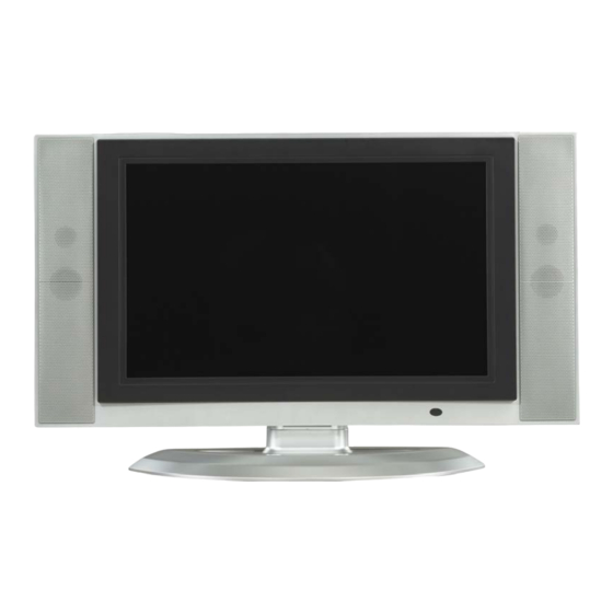
Page 2: Front & Back View
Front view Back view... -
Page 3: Function Board Position
FUNCTION BOARD POSITION (SPEAKER) (KEY BOARD) (I/R RECEIVER BOARD) (TUNER BOARD) (AUDIO BOARD) (A/D BOARD) (POWER BOARD) - Page 4 SPEAKER KEY- BOARD...
- Page 5 I/R- RECEIVER TUNER- BOARD...
-
Page 6: Audio -Board & A/D- Board
AUDIO -BOARD A/D- BOARD (ANALOG/DIGITAL BOARD) -
Page 7: I/O Port Of A/D Board
I/O PORT OF A/D BOARD 1 P/A WIRE CONNECTER 7 SCART INPUT 2 K/A WIRE CONNECTER 8 T/A WIRE CONNECTER 3 A/P WIRE CONNECTER 9 A/A WIRE CONNECTER AV INPUT 10 DVI INPUT S-VIDEO INPUT 11 D-SUB(VGA) INPUT 6. Y/Pb/Pr &Y/Cb/Cr INPUT 12 PC AUDIO INPUT... -
Page 8: Power Board
POWER BOARD 24V-OUTPUT AC-INPUT 12V-OUTPUT... -
Page 9: Wires
WIRES 1 POWER JACK 2 K/A WIRE : (KEY BOARD A/D BOARD) 3 A/A WIRE : (AUDIO BOARD A/D BOARD) 4 T/A WIRE : (TUNER BOARD A/D BOARD) 5 P/A WIRE : (PANEL A/D BOARD) 6 A/P WIRE : (A/D BOARD POWER BOARD) 7 I/P WIRE : (INVERTER BOARD POWER BOARD) - Page 10 POWER BOARD Assembly/Disassembly Instruction STEP 1 1 Turn off the main power switch on the back of the set and unplug the power cord from the outlet. Remove the 18pcs of screws (M4*10) on the edge of the back cover. remove the 2pcs of the screws (M4*8) Lift up the back cover but without...
- Page 11 A/D BOARD Assembly/Disassembly Instruction STEP 1 Remove the 6pcs screws (M2*4) on the A board cover. Change the A/D board cover , remove the 4pcs screws (M3*6) on the A/D board cover right side. STEP 2 Unplug the signal transmission line for the A/A wire connector (7PIN).
- Page 12 AUDIO BOARD & TUNER BOARD Assembly/Disassembly Instruction STEP 1 Remove the 4pcs screws (M2*4) on the A board cover. Unplug the signal transmission line for the A/A wire connector (7PIN). Unplug the signal transmission line for the speaker connector (2PIN)). To change the A/D board, remove the 4pcs of screws (M2.5*4) STEP2...
- Page 13 Assembly/Disassembly Instruction KEY BOARD & IR RECEIVER BOARD STEP1 1. Unplug the signal transmitting line for the Key board K/A wire connector (2PIN). 2. To change the key board, remove the 2pcs o screws (M3*6) STEP2 1 Unplug the signal transmitting line for the IR receiver board K/A wire connector (4PIN).
-
Page 14: Trouble Shooting List
TROUBLE SHOOTING LIST SOLUTION/ ITEM REASON REMARK PROBLEM CHANGE PART 1.Power wire not connect 1.Power wire re-connect well with the connecter. with the connecter 2. Battery no electric. of again. the Remote control 2. Change new battery. POWER WORKING 3. Power damage. 3. - Page 15 TROUBLE SHOOTING LIST SOLUTION/ ITEM REASON REMARK PROBLEM CHANGE PART 1.Battery no electric. 1. Change new battery. 2.Not scan the channel. 2. Try to scan the channel . 3.I/R-receiver board 3. Change the new I/R REMOTE damage. receiver board. CONTROL WORKING 4.
Need help?
Do you have a question about the LCT2660 and is the answer not in the manual?
Questions and answers