Table of Contents
Advertisement
Quick Links
Advertisement
Table of Contents

Related Manuals for MSI MS-6390


Summary of Contents for MSI MS-6390
- Page 1 MS-6390 (v2.X) M-ATX Mainboard Version 2.0 G52-M6390X1...
-
Page 2: Fcc-B Radio Frequency Interference Statement
Shielded interface cables and A.C. power cord, if any, must be used in order to comply with the emission limits. VOIR LA NOTICE D’INSTALLATION AVANT DE RACCORDER AU RESEAU. Micro-Star International MS-6390 Tested to comply with FCC Standard For Home or Office Use... -
Page 3: Copyright Notice
Alternatively, please try the following help resources for further guidance. Visit the MSI website for FAQ, technical guide, BIOS updates, driver updates, and other information: http://www.msi.com.tw/ Contact our technical staff at: support@msi.com.tw... -
Page 4: Safety Instructions
Safety Instructions Always read the safety instructions carefully. Keep this User’s Manual for future reference. Keep this equipment away from humidity. Lay this equipment on a reliable flat surface before setting it up. The openings on the enclosure are for air convection hence protects the equipment from overheating. -
Page 5: Table Of Contents
Safety Instructions ..................iv Chapter 1. Getting Started ................ 1-1 Mainboard Specifications ..............1-2 Mainboard Layout ................1-4 MSI Special Features ................1-5 Fuzzy Logic™ 4 ................1-5 Live BIOS™/Live Driver™ ............1-6 Live Monitor™ ................1-7 PC Alert™ 4 ................... 1-8 CPU Thermal Protection .............. - Page 6 Back Panel ..................2-10 RJ-45 LAN Jack ................2-10 Mouse/Keyboard Connector ............2-11 USB Connectors ................2-11 Serial Port Connectors: COM A, JCOM 2 ........2-12 VGA DB 15 Pin Connector ............2-12 Parallel Port Connector: LPT1 ............2-13 Audio Port Connectors ............... 2-14 Connectors ..................
- Page 7 Chapter 3. BIOS Setup ................3-1 Entering Setup ..................3-2 Control Keys ................. 3-2 Getting Help .................. 3-3 The Main Menu ................... 3-4 Standard CMOS Features ..............3-6 Advanced BIOS Features ..............3-8 Advanced Chipset Features ............... 3-12 Integrated Peripherals ................ 3-16 Power Management Features .............
-
Page 8: Chapter 1. Getting Started
Getting Started Chapter 1. Getting Started Getting Started Thank you for purchasing the MS-6390 v2.X Micro ATX ® mainboard. The MS-6390 is based on VIA KM266 & VT8235 chipsets for optimal system efficiency. Designed to fit the ad- ® vanced AMD Athlon™, Athlon™... -
Page 9: Mainboard Specifications
MS-6390 M-ATX Mainboard Mainboard Specifications ® Supports Socket A (Socket-462) for AMD Athlon™/Athlon™ XP /Duron™ processors. Supports up to 2600 or higher speed. Chipset ® KM266 North Bridge - 200/266MHz FSB. - Integrated ProSavage8 2D/3D graphic controller. - AGP 4x and high bandwidth V-link host controller. - Page 10 Getting Started 2.88Mbytes - One serial port & one serial pinheader (COM A + JCOM2) - One VGA port - One parallel port supports SPP/EPP/ECP mode - One RJ-45 LAN port - Vertical audio ports - One 3-pin SPDIF connector (Optional) - One 12-pin S-Bracket connector (Optional) - Six USB 2.0 ports (Rear * 4/ Front * 2) Audio...
-
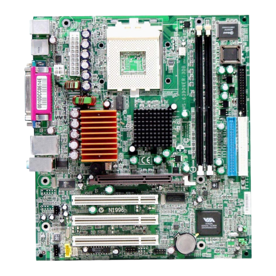
Page 11: Mainboard Layout
KM266 T: RJ45 LAN jack B: USB ports SYSFA1 Line-In Line-Out AGP Slot VT6103 PCI Slot 1 JCD1 PCI Slot 2 JAUD1 VT8235 PCI Slot 3 JCI1 BATT Codec JSLP1 JIR1 JBAT1 JFP1 JFP2 JUSB1 MS-6390 v2.X Micro ATX Mainboard... -
Page 12: Msi Special Features
After rebooting, click Turbo to apply the test result. Click Default to restore the default values. Features: MSI Logo links to the MSI Web site CPU Speed allows users to adjust the CPU speed through CPU Multiplier and FSB... -
Page 13: Live Bios™/Live Driver
BIOS/drivers online so that you don’t need to search for the correct BIOS/driver version throughout the Web site. To use the function, you need to install the “MSI Live Update 2” application. After the installation, the “MSI Live Update 2” icon (as shown on the right) will appear on the screen. -
Page 14: Live Monitor
Live Monitor™ The Live Monitor™ is a tool used to schedule the search for the latest BIOS/drivers version on the MSI Web site. To use the function, you need to install the “MSI Live Update 2” application. After the installation, the “MSI Live Monitor” icon (as shown on the right) will appear on the screen. -
Page 15: Pc Alert™ 4
MS-6390 M-ATX Mainboard PC Alert™ 4 The PC Alert 4 is a utility you can find in the CD-ROM disk. The utility is just like your PC doctor that can detect the following PC hardware status during real time operation: monitor CPU &... - Page 16 CPU and chipset. Right-click the mouse to select the skin you want to switch to. Cute MSI Reminds You... The new feature COOLER XP will work only if your mainboard supports AMD Athlon™ XP CPU.
-
Page 17: Cpu Thermal Protection
MS-6390 M-ATX Mainboard CPU Thermal Protection Aimed to prevent the CPU from overheating, MSI has developed a CPU Thermal Protection mechanism for AMD Athlon™ XP CPU platform. This CPU Thermal Protection mechanism works on a thermal signal sensor. If the mechanism senses an abnormal temperature rise, it will automatically shut down the system and the CPU temperature will then drop down and resume normal. -
Page 18: Chapter 2. Hardware Setup
Hardware Setup Chapter 2. Hardware Setup Hardware Setup This chapter provides you with the information about hard- ware setup procedures. While doing the installation, be careful in holding the components and follow the installation procedures. For some components, if you install in the wrong orientation, the components will not work properly. -
Page 19: Quick Components Guide
MS-6390 M-ATX Mainboard Quick Components Guide CPU, p.2-3 CPUFA1, p.2-17 CONN1, p.2-9 DIMM1/2, p.2-7 Back Panel FDD1, I/O, p.2-10 p.2-15 JCOM 2, p.2-12 SYSFA1, p.2-17 AGP Slot, IDE1/2, p.2-27 p.2-16 JSB1, p.2-23 SW1, p.2-26 JAUD1, p.2-21 PCI Slots, JCD1, p.2-18 p.2-27... -
Page 20: Central Processing Unit: Cpu
Hardware Setup Central Processing Unit: CPU ® The mainboard supports AMD Athlon™, Athlon™ XP and Duron™ processors in the 462 pin package. The mainboard uses a CPU socket called Socket A for easy CPU installation. When you are installing the CPU, make sure the CPU has a heat sink and a cooling fan attached on the top to prevent overheating. -
Page 21: Cpu Installation Procedures For Socket 462
MS-6390 M-ATX Mainboard CPU Installation Procedures for Socket 462 1. Please turn off the power and Open Lever unplug the power cord before installing the CPU. Sliding 90 degree Plate 2. Pull the lever sideways away from the socket. Make sure to raise the lever up to a 90- degree angle. -
Page 22: Installing Amd Athlon Cpu (Socket 462) Cooler Set
4. Connect the fan to the fan power connector provided on your mainboard. MSI Reminds You... Please apply some heat sink paste on top of CPU to dissipate the heat more effectively. -
Page 23: Setting Cpu Clock Frequency Through Jumper
MS-6390 M-ATX Mainboard Setting CPU Clock Frequency through Jumper The hardware configuration for CPU clock frequency of the motherboard is set to 133MHz by default. Therefore, to make a 100MHz CPU run at 100MHz when it is installed on the board, you have to adjust the CPU clock frequency through jumper. -
Page 24: Memory
Hardware Setup Memory The mainboard provides 2 slots for 184-pin DDR SDRAM DIMM (Double In-Line Memory Module) modules and supports the memory size up to 2GB. You can install PC2100/DDR266 or PC1600/DDR200 modules on the DDR DIMM slots (DIMM 1~2). DDR DIMM Slots (DIMM 1~2) Introduction to DDR SDRAM... -
Page 25: Dimm Module Combination
MS-6390 M-ATX Mainboard DIMM Module Combination Install at least one DIMM module on the slots. Memory modules can be installed on the slots in any order. You can install either single- or double- sided modules to meet your own needs. -
Page 26: Power Supply
Hardware Setup Power Supply The mainboard supports ATX power supply for the power system. Be- fore inserting the power supply connector, always make sure that all compo- nents are installed properly to ensure that no damage will be caused. ATX 20-Pin Power Connector: CONN1 This connector allows you to connect to an ATX power supply. -
Page 27: Back Panel
MS-6390 M-ATX Mainboard Back Panel The back panel provides the following connectors: Parallel Mouse L-In L-Out Keyboard COM A Mouse/Keyboard Connector The mainboard provides a standard PS/2 ® mouse/keyboard mini DIN connector for attaching a PS/2 ® mouse/keyboard. You can plug a PS/2 ®... -
Page 28: Usb Connectors
Hardware Setup USB Connectors The mainboard provides four UHCI (Universal Host Controller Interface) Universal Serial Bus roots for attaching USB devices such as keyboard, mouse or other USB-compatible devices. You can plug USB devices directly into the connectors. Pin Definition SIGNAL DESCRIPTION 1 2 3 4... -
Page 29: Serial Port Connectors: Com A, Jcom 2
MS-6390 M-ATX Mainboard Serial Port Connectors: COM A, JCOM 2 The mainboard provides two 9-pin serial port connectors COM A & JCOM 2. The ports are 16550A high speed communication ports that send/ receive 16 bytes FIFOs. You can attach a serial mouse or other serial devices directly to the connectors. -
Page 30: Parallel Port Connector: Lpt1
Hardware Setup Parallel Port Connector: LPT1 The mainboard provides a 25-pin female centronic connector as LPT. A parallel port is a standard printer port that supports Enhanced Parallel Port (EPP) and Extended Capabilities Parallel Port (ECP) mode. Pin Definition SIGNAL DESCRIPTION STROBE Strobe... -
Page 31: Audio Port Connectors
MS-6390 M-ATX Mainboard Audio Port Connectors Line Out is a connector for Speakers or Headphones. Line In is used for external CD player, Tape player, or other audio devices. Mic is a connec- tor for microphones. 1/8” Stereo Audio Connectors... -
Page 32: Connectors
Hardware Setup Connectors The mainboard provides connectors to connect to FDD, IDE HDD, case, modem, LAN, USB Ports, IR module and CPU/System/Power Supply FAN. Floppy Disk Drive Connector: FDD1 The mainboard provides a standard floppy disk drive connector that supports 360K, 720K, 1.2M, 1.44M and 2.88M floppy disk types. FDD1 2-15... -
Page 33: Hard Disk Connectors: Ide1 & Ide2
MS-6390 M-ATX Mainboard Hard Disk Connectors: IDE1 & IDE2 The mainboard has a 32-bit Enhanced PCI IDE and Ultra ATA 66/100/ 133 controller that provides PIO mode 0~4, Bus Master, and Ultra ATA 66/ 100/133 function. You can connect up to four hard disk drives, CD-ROM, 120MB Floppy (reserved for future BIOS) and other devices. -
Page 34: Fan Power Connectors: Cpufa1/Sysfa1
GND. If the mainboard has a System Hardware Monitor chipset onboard, you must use a specially designed fan with speed sensor to take advantage of the CPU fan control. SENSOR +12V CPUFA1 SENSOR +12V SYSFA1 MSI Reminds You... Always consult the vendors for proper CPU cooling fan. 2-17... -
Page 35: Cd-In Connector: Jcd1
MS-6390 M-ATX Mainboard CD-In Connector: JCD1 This connector is provided for CD-ROM audio. JCD1 Chassis Intrusion Switch Connector: JCI1 This connector is connected to a 2-pin chassis switch. If the chassis is opened, the switch will be short. The system will record this status and show a warning message on the screen. -
Page 36: Power Saving Switch Connector: Jslp1
Hardware Setup Power Saving Switch Connector: JSLP1 Attach a power saving switch to this connector. Pressing the switch once will have the system enter the sleep/suspend state. JSLP1 IrDA Infrared Module Header: JIR1 The connector allows you to connect to IrDA Infrared module. You must configure the setting through the BIOS setup to use the IR function. -
Page 37: Front Panel Connectors: Jfp1, Jfp2
MS-6390 M-ATX Mainboard Front Panel Connectors: JFP1, JFP2 The mainboard provides two front panel connectors for electrical con- nection to the front panel switches and LEDs. The JFP1 is compliant with ® Intel Front Panel I/O Connectivity Design Guide. Power... -
Page 38: Front Panel Audio Connector: Jaud1
Left channel audio signal to front panel AUD_RET_L Left channel audio signal return from front panel MSI Reminds You... If you don’t want to connect to the front audio header, pins 5 & 6, 9 & 10 have to be jumpered in order to have signal output directed to the rear audio ports. -
Page 39: Spdif Connector: Jsp1 (Optional)
MS-6390 M-ATX Mainboard SPDIF Connector: JSP1 (Optional) The connector is used to connect SPDIF (Sony & Philips Digital Inter- connect Format) interface for digital audio transmission. An optional SPDIF Bracket is available upon request. JSP1 (optional) Pin Definition SIGNAL DESCRIPTION... -
Page 40: S-Bracket Connector: Jsb1 (Optional)
Hardware Setup S-Bracket Connector: JSB1 (Optional) This connector allows you to connect the optional S-Bracket for Sony & Philips Digital Interface (SPDIF). The S-Bracket offers 2 SPDIF jacks for digital audio transmission (one for optical fiber connection and the other for coaxial), and 2 analog Line-Out jacks for 4-channel audio output. -
Page 41: Front Usb Connector: Jusb1
MS-6390 M-ATX Mainboard Front USB Connector: JUSB1 The mainboard provides one USB 2.0 pin header JUSB1 (optional USB ® 2.0 bracket available) that is compliant with Intel I/O Connectivity Design Guide. USB 2.0 technology increases data transfer rate up to a maximum throughput of 480Mbps, which is 40 times faster than USB 1.1, and is ideal... -
Page 42: Jumpers
JBAT1 Clear Data Keep Data MSI Reminds You... You can clear CMOS by shorting 2-3 pin while the system is off. Then return to 1-2 pin position. Avoid clearing the CMOS while the system is on; it will damage the mainboard. -
Page 43: Fsb Clock Jumper: Sw1
MS-6390 M-ATX Mainboard FSB Clock Jumper: SW1 These two jumpers provide 100MHz and 133MHz Front Side Bus fre- quency selection for overclocking purpose. FSB = 100MHz FSB = 133MHz 2-26... -
Page 44: Slots
Hardware Setup Slots The motherboard provides one AGP slot, three 32-bit Master PCI bus slots, and one CNR slot. AGP Slot PCI Slots CNR Slot AGP (Accelerated Graphics Port) Slot The AGP slot allows you to insert the AGP graphics card. AGP is an interface specification designed for the throughput demands of 3D graphics. -
Page 45: Pci Interrupt Request Routing
MS-6390 M-ATX Mainboard PCI Interrupt Request Routing The IRQ, acronym of interrupt request line and pronounced I-R-Q, are hardware lines over which devices can send interrupt signals to the microprocessor. The PCI IRQ pins are typically connected to the PCI bus INT... -
Page 46: Chapter 3. Bios Setup
BIOS Setup Chapter 3. BIOS Setup BIOS Setup This chapter provides information on the BIOS Setup pro- gram and allows you to configure the system for optimum use. You may need to run the Setup program when: An error message appears on the screen during the system booting up, and requests you to run SETUP. -
Page 47: Entering Setup
MS-6390 M-ATX Mainboard Entering Setup Power on the computer and the system will start POST (Power On Self Test) process. When the message below appears on the screen, press <DEL> key to enter Setup. Press DEL to enter SETUP If the message disappears before you respond and you still wish to enter Setup, restart the system by turning it OFF and On or pressing the RESET button. -
Page 48: Getting Help
Press <Esc> to exit the Help screen. MSI Reminds You... The items under each BIOS category described in this chapter are under continuous update for better system performance. -
Page 49: The Main Menu
MS-6390 M-ATX Mainboard The Main Menu Once you enter AwardBIOS CMOS Setup Utility, the Main Menu will appear on the screen. The Main Menu displays twelve configurable functions and two exit choices. Use arrow keys to move among the items and press <Enter>... - Page 50 BIOS Setup PNP/PCI Configurations This entry appears if your system supports PnP/PCI. PC Health Status This entry shows your PC health status. Frequency/Voltage Control Use this menu to specify your settings for frequency/voltage control. Load Fail-Safe Defaults Use this menu to load the BIOS default values for minimal but stable system performance.
-
Page 51: Standard Cmos Features
MS-6390 M-ATX Mainboard Standard CMOS Features The items inside Standard CMOS Features menu are divided into 10 categories. Each category includes none, one or more setup items. Use the arrow keys to highlight the item you want to modify and use the <PgUp> or <PgDn>... - Page 52 BIOS Setup will not work properly if you enter improper information for this category. If your hard disk drive type is not matched or listed, you can use Manual to define your own drive type manually. If you select Manual, related information is asked to be entered to the follow- ing items.
-
Page 53: Advanced Bios Features
MS-6390 M-ATX Mainboard Advanced BIOS Features Quick Boot Setting the item to Enabled allows the system to boot within 5 seconds since it will skip some check items. Available options: Enabled, Disabled. Virus Warning The item is to set the Virus Warning feature for IDE Hard Disk boot sector protection. - Page 54 The system will boot from the Network drive. Disabled Disable this sequence. MSI Reminds You... Available settings for “1st/2nd/3rd Boot Device” vary depend- ing on the bootable devices you have installed. For example, if you did not install a floppy drive, the setting “Floppy” does not show up.
- Page 55 MS-6390 M-ATX Mainboard Boot Up NumLock Status This setting is to set the Num Lock status when the system is powered on. Setting to On will turn on the Num Lock key when the system is powered on. Setting to Off will allow users to use the arrow keys on the numeric keypad.
- Page 56 BIOS Setup APIC Mode This setting is used to enable or disable the APIC (Advanced Programmable Interrupt Controller). Due to compliance to PC2001 design guide, the system is able to run in APIC mode. Enabling APIC mode will expand available IRQs resources for the system.
-
Page 57: Advanced Chipset Features
MS-6390 M-ATX Mainboard Advanced Chipset Features MSI Reminds You... Change these settings only if you are familiar with the chipset. DRAM Clock/Drive Control Press <Enter> to enter the sub-menu and the following screen appears: Current FSB/DRAM Frequency This item shows the current clock frequency of the specified components. - Page 58 BIOS Setup DRAM Clock Use this item to configure the clock frequency of the installed DRAM. Settings options: By SPD, 100MHz, 133MHz. DRAM Timing Selects whether DRAM timing is controlled by the SPD (Serial Presence Detect) EEPROM on the DRAM module. Setting to By SPD enables DRAM CAS Latency, Bank Interleave, Precharge to Active (Trp), Active to Precharge (Tras), and Active to CMD (Trcd) automatically to be de- termined by BIOS based on the configurations on the SPD.
- Page 59 MS-6390 M-ATX Mainboard DRAM Command Rate This setting controls the SDRAM command rate. Selecting 1T Command allows SDRAM signal controller to run at 1T (T=clock cycles) rate. Se- lecting 2T Command makes SDRAM signal controller run at 2T rate. 1T is faster than 2T.
- Page 60 BIOS Setup AGP Driving Value This item specifies an AGP driving force. AGP Fast Write This field enables or disables the AGP Fast Write feature. The Fast Write technology allows the CPU to write directly to the graphics card without passing anything through the system memory and improves the AGP speed.
-
Page 61: Integrated Peripherals
MS-6390 M-ATX Mainboard Integrated Peripherals VIA OnChip IDE Device Press <Enter> to enter the sub-menu and the following screen appears: IDE DMA Transfer Access Set this option to Enabled to specify that the IDE controller on the PCI local bus has bus mastering capability. Setting options: Disabled, Enabled. - Page 62 BIOS Setup Primary/Secondary Master/Slave PIO The four IDE PIO (Programmed Input/Output) fields let you set a PIO mode (0-4) for each of the four IDE devices that the onboard IDE inter- face supports. Modes 0 through 4 provide successively increased performance.
- Page 63 MS-6390 M-ATX Mainboard dem is used, the onboard MC’97 (Modem Codec’97) controller will be enabled; if not, it is disabled. Disable the controller if you want to use other controller cards to connect to a modem. Setting options: Auto, Disabled.
- Page 64 BIOS Setup UART Mode Select This setting allows you to specify the operation mode for serial port 2. Setting options: IrDA, ASKIR, Normal. Normal RS-232C Serial Port IrDA IrDA-compliant Serial Infrared Port ASKIR Amplitude Shift Keyed Infrared Port RxD, TxD Active This setting controls the receiving and transmitting speed of the IR pe- ripheral in use.
- Page 65 MS-6390 M-ATX Mainboard ECP + EPP: Extended Capability Port + Enhanced Parallel Port To operate the onboard parallel port as Standard Parallel Port only, choose “SPP.” To operate the onboard parallel port in the EPP mode simultaneously, choose “EPP.” By choosing “ECP”, the onboard paral- lel port will operate in ECP mode only.
-
Page 66: Power Management Features
BIOS Setup Power Management Features MSI Reminds You... S3-related functions described in this section are available only when your BIOS supports S3 sleep mode. IPCA Function This item is to activate the ACPI (Advanced Configuration and Power Man- agement Interface) function. If your operating system is ACPI-aware, such as Windows 98SE/2000/ME, select Enabled. - Page 67 MS-6390 M-ATX Mainboard energy. The information stored in memory will be used to restore the system when a “wake up” event occurs. Power Management Option This item is used to select the degree (or type) of power saving and is related to these modes: Suspend Mode and HDD Power Down.
- Page 68 These fields specify whether the system will be awakened from power saving modes when activity or input signal of the specified hardware peripheral or component is detected. MSI Reminds You... You need to install a modem card supporting power on function for “Wake Up On Ring” function.
- Page 69 MS-6390 M-ATX Mainboard Date (of Month)/Resume Time (hh:mm:ss) If Resume By Alarm is set to Enabled, the system will automatically re- sume (boot up) on a specific date/hour/minute/second specified in these fields. Available settings for each item are: Alarm Date...
-
Page 70: Pnp/Pci Configurations
BIOS Setup PNP/PCI Configurations This section describes configuring the PCI bus system and PnP (Plug & Play) feature. PCI, or Peripheral Component Interconnect, is a system which allows I/O devices to operate at speeds nearing the speed the CPU itself uses when communicating with its special components. - Page 71 MS-6390 M-ATX Mainboard IRQ Resources The items are adjustable only when Resources Controlled By is set to Manual. Press <Enter> and you will enter the sub-menu of the items. IRQ Resources list IRQ 3/4/5/7/9/10/11/12/14/15 for users to set each IRQ a type depending on the type of device using the IRQ.
-
Page 72: Pc Health Status
BIOS Setup PC Health Status This section shows the status of your CPU, fan, overall system status, etc. Monitor function is available only if there is hardware monitoring mecha- nism onboard. Case Open Warning The field enables or disables the feature of recording the chassis intrusion status and issuing a warning message if the chassis is once opened. -
Page 73: Frequency/Voltage Control
MS-6390 M-ATX Mainboard Frequency/Voltage Control Use this menu to specify your settings for frequency/voltage control. Auto Detect DIMM/PCI Clk This item is used to auto detect the PCI/DIMM slots. When set to Enabled, the system will remove (turn off) clocks from empty PCI/DIMM slots to mini- mize the electromagnetic interference (EMI). -
Page 74: Load Fail-Safe/Optimized Defaults
BIOS Setup Load Fail-Safe/Optimized Defaults The two options on the main menu allow users to restore all of the BIOS settings to the default Fail-Safe or Optimized values. The Optimized Defaults are the default values set by the mainboard manufacturer specifically for op- timal performance of the mainboard. -
Page 75: Set Supervisor/User Password
MS-6390 M-ATX Mainboard Set Supervisor/User Password When you select this function, a message as below will appear on the screen: Type the password, up to six characters in length, and press <Enter>. The password typed now will replace any previously set password from CMOS memory. -
Page 76: Appendix: Using 4- Or 6-Channel Audio Function
Using 4- or 6-Channel Audio Function Appendix: Using 4- or 6-Channel Audio Function The motherboard is equipped with Realtek ALC650 chip, which pro- vides support for 6-channel audio output, including 2 Front, 2 Rear, 1 Center and 1 Subwoofer channel. ALC650 allows the board to attach 4 or 6 speakers for better surround sound effect. -
Page 77: Installing The Audio Driver
MS-6390 M-ATX Mainboard Installing the Audio Driver You need to install the driver for Realtek ALC650 chip to function properly before you can get access to 4-/6-channel audio operations. Follow the pro- cedures described below to install the drivers for different operating systems. -
Page 78: Using 4- Or 6-Channel Audio Function
Using 4- or 6-Channel Audio Function 3. Click Next to start installing files into the system. Click here 4. Click Finish to restart the system. Select this option Click here... -
Page 79: Using The Optional S-Bracket
MS-6390 M-ATX Mainboard Using 4- or 6-Channel Audio Function After installing the audio driver, you are able to use the 4-/6-channel audio feature now. To enable 4- or 6-channel audio operation, first connect 4 or 6 speakers to the appropriate audio connectors, and then select 4- or 6- channel audio setting in the software utility. - Page 80 Using 4- or 6-Channel Audio Function 5. Select or clear the Default Phonejack check box to decide which audio devices you wish to use for audio outputs. The instructions shown on the Speaker Configuration screen may vary depending on how you set the options of No. of Speaker and Default Phonejack.
- Page 81 MS-6390 M-ATX Mainboard Connecting the Speakers When you have set the Multi-Channel Audio Function mode properly in the software utility, connect your speakers to the correct phonejacks in accordance with the setting in software utility. 2-Channel Mode for Stereo-Speaker Output...
- Page 82 Using 4- or 6-Channel Audio Function 4-Channel Mode for 4-Speaker Output When this mode is selected, plug the two front speakers to the Line Out connector on the back panel, and the other two rear speakers to the Line Out connector on the S-Bracket. Refer to the following diagram and caption for the function of each phonejack on the back panel and S-Bracket when 4-Channel mode is selected.
- Page 83 MS-6390 M-ATX Mainboard 6-Channel Mode for 6-Speaker Output When this mode is selected, plug the two front speakers to the Line Out connector on the back panel, and the other two rear speakers to the Line Out connector on the S-Bracket.
- Page 84 S-Bracket. S-Bracket Optical SPDIF jack Coaxial SPDIF jack Plug MSI Reminds You... Some commonly-used audio output for- mats (midi, wav,..etc.) may not be able to be output from the SPDIF jacks of the S-Bracket. To convert these audio formats as SPDIF output: 1.
-
Page 85: Using The Back Panel Only
MS-6390 M-ATX Mainboard Using the Back Panel only In addition to a default 2-channel analog audio output function, the au- dio connectors on the Back Panel also provide 4- or 6-channel analog audio output function if a proper setting is made in the software utility. - Page 86 Using 4- or 6-Channel Audio Function Connecting the Speakers When you have set the Multi-Channel Audio Function mode properly in the software utility, connect your speakers to the correct phonejacks in accordance with the setting in software utility. 2-Channel Mode for Stereo-Speaker Output Refer to the following diagram and caption for the function of each phonejack on the back panel when 2-Channel Mode is selected.
- Page 87 MS-6390 M-ATX Mainboard 4-Channel Mode for 4-Speaker Output The audio jacks on the back panel always provide 2-channel analog audio output function, however these audio jacks can be transformed to 4- or 6- channel analog audio jacks by selecting the corresponding multi-channel operation from No.
- Page 88 * Both Line In and MIC function are converted to Line Out function when 4- Channel Mode for 6-Speaker Output is selected. MSI Reminds You... If the Center and Subwoofer speaker exchange their audio chan- nels when you play video or music on the computer, a converter may be required to exchange center and subwoofer audio signals.
-
Page 89: Testing The Connected Speakers
MS-6390 M-ATX Mainboard Testing the Connected Speakers To ensure that 4- or 6-channel audio operation works properly, you may need to test each connected speaker to make sure every speaker work properly. If any speaker fails to sound, then check whether the cable is inserted firmly to the connector or replace the bad speakers with good ones. - Page 90 Using 4- or 6-Channel Audio Function 4. While you are testing the speakers in 6-Channel Mode, if the sound com- ing from the center speaker and subwoofer is swapped, you should select Swap Center/Subwoofer Output to readjust these two channels. Select this function A-15...
-
Page 91: Playing Karaok
MS-6390 M-ATX Mainboard Playing KaraOK The KaraOK function will automatically remove human voice (lyrics) and leave melody for you to sing the song. Note that this function applies only for 2-channel audio operation. Playing KaraOK 1. Click the audio icon from the window tray at the lower-right corner of the screen. -
Page 92: Troubleshooting
A: Phoenix & Award already merged as one company. All MSI motherboards using Award BIOS come with Phoenix logo stickers. Q: I used my MSI motherboard and got an error message, "Primary IDE Channel No 80 Conductor Cable Installed" while the system detected hard drives. - Page 93 2. Try to clear the CMOS If problem still persists, ask your reseller for new BIOS chip or contact one of MSI office near your place for new BIOS chip http:// www.msi.com.tw/contact/main.htm Q: Should I update my BIOS, once a new BIOS is released? A: A new BIOS is usually released due to the following reasons: 1.
- Page 94 BIOS, unless you really have to. Q: How do I update the BIOS? A: Please refer to http://www.msi.com.tw/support/bios/note.htm for details. Q: How do I identify the BIOS version? A: Upon boot-up, the 1st line appearing after the memory count is the BIOS version.
- Page 95 MS-6390 M-ATX Mainboard Q: After I flashed the BIOS and rebooted the system, the screen went blank. A: For AMI BIOS Rename the desired AMI BIOS file to AMIBOOT.ROM and save it on a floppy disk. e.g. Rename A569MS23.ROM to AMIBOOT.ROM Insert this floppy disk in the floppy drive.
-
Page 96: Glossary
Glossary Glossary Glossary ACPI (Advanced Configuration & Power Interface) This power management specification enables the OS (operating system) to control the amount of power given to each device attached to the computer. Windows 98/98SE, Windows 2000 and Windows ME can fully support ACPI to allow users managing the system power flexibly. - Page 97 MS-6390 M-ATX Mainboard contents of frequently accessed RAM locations and the addresses where these data items are stored. Chipset A collection of integrated chips designed to perform one or more related functions. For example, a modem chipset contains all the primary circuits for transmitting and receiv- ing data;...
- Page 98 Glossary ECC Memory (Error Correcting Code Memory) A type of memory that contains special circuitry for testing the accuracy of data and correcting the errors on the fly. EEPROM Acronym for Electrically Erasable Programmable Read-Only Memory. An EEPROM is a special type of PROM that can be erased by exposing it to an electrical charge. Like other types of PROM, EEPROM retains its contents even when the power is turned off.
- Page 99 MS-6390 M-ATX Mainboard IDE (Integrated Drive Electronics) A type of disk-drive interface widely used to connect hard disks, CD-ROMs and tape drives to a PC, in which the controller electronics is integrated into the drive itself, eliminating the need for a separate adapter card. The IDE interface is known as the ATA (AT Attachment) specification.
- Page 100 Glossary LBA (Logical Block Addressing) Logical block addressing is a technique that allows a computer to address a hard disk larger than 528 megabytes. A logical block address is a 28-bit value that maps to a specific cylinder-head-sector address on the disk. 28 bits allows sufficient variation to specify addresses on a hard disk up to 8.4 gigabytes in data storage capacity.
- Page 101 MS-6390 M-ATX Mainboard PS/2 Port A type of port developed by IBM for connecting a mouse or keyboard to a PC. The PS/2 port supports a mini DIN plug containing just 6 pins. Most modern PCs equipped with PS/2 ports so that the special port can be used by another device, such as a modem.
Need help?
Do you have a question about the MS-6390 and is the answer not in the manual?
Questions and answers