
Subscribe to Our Youtube Channel
Related Manuals for MSI MS-6367


Summary of Contents for MSI MS-6367
-
Page 1: Chapter 1. Introduction
All manuals and user guides at all-guides.com Introduction Chapter 1. Introduction Chapter 1. Getting Started Getting Started ® TOPICS Mainboard Specification Mainboard Layout Quick Components Guide... -
Page 2: Mainboard Specification
All manuals and user guides at all-guides.com Chapter 1 Mainboard Specification ® Chipset ® 1.5V only ® Main Memory Slots 1.5V On-Board IDE... - Page 3 All manuals and user guides at all-guides.com Introduction Audio Video Network (Optional) On-Board Peripherals BIOS...
- Page 4 All manuals and user guides at all-guides.com Chapter 1 Dimension Mounting Others...
-
Page 5: Mainboard Layout
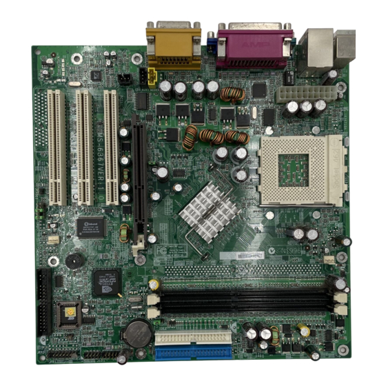
SYSFAN1 JFP1 FDD1 MS-6367 Micro ATX Mainboard Note: One unique MAC Address label is attached on PCI Slot 3 of the motherboard that supports LAN. The label looks like the picture below but its number varies depending on the board you purchased. -
Page 6: Quick Components Guide
All manuals and user guides at all-guides.com Chapter 1 Quick Components Guide... -
Page 7: Hardware Setup
All manuals and user guides at all-guides.com Hardware Setup Chapter 2. Hardware Setup Hardware Setup TOPICS... -
Page 8: Central Processing Unit (Cpu)
All manuals and user guides at all-guides.com Chapter 2 Central Processing Unit: CPU ® Make sure the CPU has a Heat Sink and a cooling fan attached on the top to prevent overheating. Open Lever Sliding Plate Cut edge Press down the CPU Close Lever... - Page 9 All manuals and user guides at all-guides.com Hardware Setup Thermal Issue for CPU WARNING! 600MHz and above...
- Page 10 All manuals and user guides at all-guides.com Chapter 2 then FSB = 100MHz FSB = 133MHz Overclocking WARNING! We do not guarantee the damages or risks caused by inadequate operation or beyond product specifications.
- Page 11 All manuals and user guides at all-guides.com Hardware Setup Memory...
- Page 12 All manuals and user guides at all-guides.com Chapter 2 Slot Momory Module Total Memory Slot 1 64MB, 128MB, 256MB, 64MB~512MB (Bank 0 & 1) 512MB Slot 2 64MB, 128MB, 256MB, 64MB~512MB (Bank 2 & 3) 512MB Maximum System Memory Supported 64MB~1GB Warning: We don’t recommend to install DOUBLE-SIDED DDR266 module on DDR 3 slot...
-
Page 13: Power Supply
All manuals and user guides at all-guides.com Hardware Setup Power Supply SIGNAL SIGNAL... -
Page 14: Back Panel
All manuals and user guides at all-guides.com Chapter 2 Back Panel ® ® ® Pin Definition SIGNAL DESCRIPTION... - Page 15 All manuals and user guides at all-guides.com Hardware Setup ® ® ® Pin Definition SIGNAL DESCRIPTION USB Port Description SIGNAL DESCRIPTION...
- Page 16 All manuals and user guides at all-guides.com Chapter 2 Pin Definition SIGNAL DESCRIPTION Signal Description (DB 15-pin) 2-10...
- Page 17 All manuals and user guides at all-guides.com Hardware Setup Pin Definition SIGNAL DESCRIPTION 2-11...
- Page 18 All manuals and user guides at all-guides.com Chapter 2 Pin Definition SIGNAL DESCRIPTION Line Out Line In 1/8” Stereo Audio Connectors 2-12...
- Page 19 All manuals and user guides at all-guides.com Hardware Setup Connectors 2-13...
- Page 20 All manuals and user guides at all-guides.com Chapter 2 ® IDE1 IDE2 40 39 40 39 2-14...
- Page 21 All manuals and user guides at all-guides.com Hardware Setup Reset Switch Power Switch Speaker Power Buzzer HDD LED Keylock Power Switch Reset Switch Power LED Speaker 2-15...
- Page 22 All manuals and user guides at all-guides.com Chapter 2 HDD LED Keylock 2-16...
- Page 23 All manuals and user guides at all-guides.com Hardware Setup GND L GND L 2-17...
- Page 24 All manuals and user guides at all-guides.com Chapter 2 compliant with Intel Front Panel I/O Connectivity Design Guide. J9/10 Pin Definition SIGNAL 2-18...
- Page 25 All manuals and user guides at all-guides.com Hardware Setup SENSOR +12V SENSOR +12V Note: 2-19...
- Page 26 All manuals and user guides at all-guides.com Chapter 2 JSPDIF1 Pin Definition SIGNAL Connected to JSPDIF1 2-20...
- Page 27 All manuals and user guides at all-guides.com Hardware Setup compliant with Intel Front Panel I/O Connectivity Design Guide Pin Definition SIGNAL DESCRIPTION Note: 2-21...
- Page 28 All manuals and user guides at all-guides.com Chapter 2 Jumpers Clear Data Keep Data WARNING! 2-22...
- Page 29 All manuals and user guides at all-guides.com Hardware Setup Slots 1.5V only supports 4x 1.5V AGP card WARNING 2-23...
- Page 30 All manuals and user guides at all-guides.com Chapter 2 Order 1 Order 2 Order 3 Order 4 INT E# INT A# PCI Slot 1 INT A# INT B# INT C# INT D# PCI Slot 2 INT B# INT C# INT D# INT A# PCI Slot 3 INT C# INT D# INT A# INT B# PCI Slot 1~3: Bus Master.
Need help?
Do you have a question about the MS-6367 and is the answer not in the manual?
Questions and answers