
Related Manuals for MSI MS-6318


Summary of Contents for MSI MS-6318
- Page 1 MICRO-STAR INTERNATIONAL MS-6318 (v5.X) Micro ATX Mainboard Version 5.0 G52-MA00462...
- Page 2 Shielded interface cables and A.C. power cord, if any, must be used in order to comply with the emission limits. VOIR LA NOTICE D’INSTALLATION AVANT DE RACCORDER AU RESEAU. Micro-Star International MS-6318 Tested to comply with FCC Standard For Home or Office Use...
- Page 3 Edition Oct. 2001 Copyright Notice The material in this document is the intellectual property of MICRO- STAR INTERNATIONAL. We take every care in the preparation of this document, but no guarantee is given as to the correctness of its contents. Our products are under continual improvement and we re- serve the right to make changes without notice.
- Page 4 Safety Instructions Always read the safety instructions carefully. Keep this User’s Manual for future reference. Keep this equipment away from humidity. Lay this equipment on a reliable flat surface before setting it up. The openings on the enclosure are for air convection hence protects the equipment from overheating.
-
Page 5: Table Of Contents
CONTENTS Chapter 1. Introduction ............... 1-1 Mainboard Specification ............1-2 Mainboard Layout ..............1-4 Quick Components Guide ............1-5 Key Features ................1-6 Chapter 2. Hardware Setup ............2-1 Central Processing Unit: CPU ........... 2-2 CPU Installation Procedures ..........2-2 CPU Core Speed Derivation Procedure ........ - Page 6 Modem-In Connector: JPHONE ......... 2-14 Wake On LAN Connector: JWOL1 ........2-15 Wake On Ring Connector: JMDM1 ........2-15 Front Panel Connector: JFP1 or JFP2 ....... 2-16 Front Audio Header: JAUDIO1 ........... 2-17 Front USB Connector: USB1 or USB3 ......2-18 IrDA Infrared Module Header: IR2 ........
- Page 7 Save & Exit Setup ..............3-30 Exit Without Saving ..............3-31 Appendix: Glossary ..............A-1...
-
Page 8: Chapter 1. Introduction
Introduction Chapter 1. Introduction Thank you for purchasing the MS-6318 v5.X Micro ATX mainboard. The MS-6318 is a superior computer mainboard based on VIA ® Apollo Pro133T chipset for optimal system efficiency. Designed to fit the advanced Intel ® Pentium III/Celeron™/Coppermine™/Tualatin™, and VIA... -
Page 9: Mainboard Specification
Chapter 1 Mainboard Specification Supports Socket 370 for Intel Pentium III/Celeron™/Coppermine™/ ® ® Tualatin™, and VIA C3™ processors. ® Supports 600MHz ~ 1.2 GHz CPU. Chipset 694T chipset (520 BGA) ® - Supports 66/100/133MHz FSB. - AGP 4x and PCI plus Advanced ECC Memory Controller. - Supports PC100/133 SDRAM, VCM &... - Page 10 Introduction 2.88Mbytes. - 2 serial ports (COM A + COM B). - 1 parallel port supports SPP/EPP/ECP mode. - 4 USB ports (Rear * 2/ Front * 2). - 1 audio/game port. Audio DirectSound AC97 audio integrated. Sigmatel 9708T software audio (optional). Creative CT5880 hardware audio (optional).
-
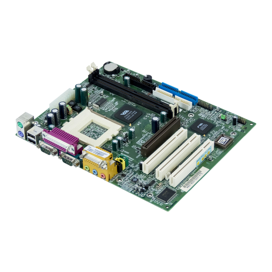
Page 11: Mainboard Layout
JGL1 Bottom: Line-Out Line-In JFP2 AGP Slot JFP1 (Optional) CODEC PCI Slot 1 USB3 VT82C686B JUSBV2 PCI Slot 2 JAUDIO1 JMDM1 USB1 Creative JBAT1 JWOL1 CT5880 PCI Slot 3 (Optional) (Optional) BIOS ISA Slot (Optional) MS-6318 v5.X Micro ATX Mainboard... -
Page 12: Quick Components Guide
Introduction Quick Components Guide Component Function Reference JWR1 ATX power connector See p. 2-6 JKBMS1 Mouse/keyboard connector See p. 2-7 USB Connectors Connecting to USB devices See p. 2-8 COM A & COM B Serial port connector See p. 2-9 L P T 1 Parallel port connector See p. -
Page 13: Key Features
Chapter 1 Key Features Micro ATX Form Factor Audio Chip Integrated Support DMI(Desktop Management Interface) through BIOS LAN Wake Up Function Modem (Internal/External) Ring Wake Up Function Suspend to RAM/Disk Support PC2001... -
Page 14: Chapter 2. Hardware Setup
Hardware Setup C h a p t e r Hardware Setup This chapter provides you with the information about hardware setup procedures. While doing the installation, be careful in holding the components and follow the installation procedures. For some components, if you install in the wrong orientation, the components will not work properly. -
Page 15: Central Processing Unit: Cpu
Chapter 2 Central Processing Unit: CPU ® ® The mainboard supports Intel Pentium III/Celeron™/Coppermine™/ ® Tualatin™, VIA C3™ processors and uses a CPU socket called PGA370 for easy CPU installation. When you are installing the CPU, make sure the CPU has a heat sink and a cooling fan attached on the top to prevent overheating. -
Page 16: Cpu Core Speed Derivation Procedure
Hardware Setup CPU Core Speed Derivation Procedure CPU Clock 100MHz Core/Bus ratio then CPU core speed Host Clock x Core/Bus ratio 100MHz x 9 900MHz Overclocking This motherboard is designed to support overclocking. However, please make sure your components are able to WARNING! tolerate such abnormal setting, while doing overclocking. -
Page 17: Memory Installation
Chapter 2 Memory Installation Memory Bank Configuration The mainboard supports a maximum memory size of 1GB. It provides two 168-pin unbuffered SDRAM DIMM (Double In-Line Memory Module) slots and supports 8MB to 512MB technology. Synchronous DRAM is a type of dynamic RAM memory chip that has been widely used starting in the latter part of the 1990s. -
Page 18: Memory Installation Procedures
Hardware Setup Memory Installation Procedures Installing DIMM Modules You can install memory modules in any combination as follows: Slot Memory Module Total Memory Slot 1 8MB~512MB 8MB~512MB (Bank 0 & Bank 1) Slot 2 8MB~512MB 8MB~512MB (Bank 2 & Bank 3) Total System Memory 8MB~1GB Memory Population Rules... -
Page 19: Power Supply
Chapter 2 Power Supply The mainboard supports ATX power supply for the power system. Be- fore inserting the power supply connector, always make sure that all compo- nents are installed properly to ensure that no damage will be caused. ATX 20-Pin Power Connector: JWR1 This connector allows you to connect to an ATX power supply. -
Page 20: Back Panel
Hardware Setup Back Panel The Back Panel provides the following connectors: Parallel Midi/Joystick Mouse Keyboard COM A COM B L-out L-in MIC Mouse Connector: JKBMS1 ® The mainboard provides a standard PS/2 mouse mini DIN connector for ® ® attaching a PS/2 mouse. -
Page 21: Keyboard Connector: Jkbms1
Chapter 2 Keyboard Connector: JKBMS1 ® The mainboard provides a standard PS/2 keyboard mini DIN connector ® ® for attaching a PS/2 keyboard. You can plug a PS/2 keyboard directly into this connector. Pin Definition SIGNAL DESCRIPTION Keyboard DATA Keyboard DATA No connection Ground Keyboard Clock... -
Page 22: Serial Port Connector: Com A & Com B
Hardware Setup Serial Port Connector: COM A & COM B The mainboard offers two 9-pin male DIN connectors for serial port COM A and COM B. The ports are 16550A high speed communication ports that send/receive 16 bytes FIFOs. You can attach a serial mouse or other serial devices directly to them. -
Page 23: Parallel Port Connector: Lpt1
Chapter 2 Parallel Port Connector: LPT1 The mainboard provides a 25-pin female centronic connector for LPT. A parallel port is a standard printer port that supports Enhanced Parallel Port (EPP) and Extended Capabilities Parallel Port (ECP) mode. Pin Definition SIGNAL DESCRIPTION STROBE Strobe... -
Page 24: Connectors
Hardware Setup Connectors The mainboard provides connectors to connect to FDD, IDE HDD, case, modem, LAN, USB Ports, IR module and CPU/System FAN. Floppy Disk Drive Connector: FDD1 The mainboard provides a standard floppy disk drive connector that supports 360K, 720K, 1.2M, 1.44M and 2.88M floppy disk types. 2-11... -
Page 25: Hard Disk Connectors: Ide1 & Ide2
Chapter 2 Hard Disk Connectors: IDE1 & IDE2 The mainboard has a 32-bit Enhanced PCI IDE and Ultra DMA 33/66/100 controller that provides PIO mode 0~4, Bus Master, and Ultra DMA/33/66/100 function. You can connect up to four hard disk drives, CD-ROM, 120MB Floppy (reserved for future BIOS) and other devices. -
Page 26: Fan Power Connectors: Cpufan/Sysfan
Hardware Setup Fan Power Connectors: CPUFAN/SYSFAN The CPUFAN (processor fan) & SYSFAN (system fan) support system cooling fan with +12V. It supports three-pin head connector. When connect- ing the wire to the connectors, always take note that the red wire is the positive and should be connected to the +12V, the black wire is Ground and should be connected to GND. -
Page 27: Cd-In Connector: Jcd1
Chapter 2 CD-In Connector: JCD1 The connector is for CD-ROM audio connector. Aux Line-In Connector: JAUX1 The connector is for DVD add-on card with Line-in connector. Modem-In Connector: JPHONE The connector is for modem with internal audio connector. JCD1 JAUX1 Mono_Out JPHONE Phone_In... -
Page 28: Wake On Lan Connector: Jwol1
Hardware Setup Wake On LAN Connector: JWOL1 This connector allows you to connect to a LAN card with Wake On LAN function. You can wake up the computer via remote control through a local area network. MP_WAKEUP 5VSB JWOL1 Wake On Ring Connector: JMDM1 This connector allows you to connect to a modem card with Wake On Ring function. -
Page 29: Front Panel Connector: Jfp1 Or Jfp2
Chapter 2 Front Panel Connector: JFP1 or JFP2 The mainboard provides one front panel connector for electrical connec- tion to the front panel switches and LEDs. Users can choose either the JFP1 or the JFP2 depending on their needs.The difference between JFP1 & JFP2 is that ®... -
Page 30: Front Audio Header: Jaudio1
Hardware Setup Front Audio Header: JAUDIO1 This connector allows you to connect to the front panel audio. JAUDIO1 JAUDIO1 Pin Definition Description Description Active Line Out (R) Active Line Out (L) GND (ALO) GND (ALO) GND (+12) GND (+12) +12V (1A) (Cut) GND (MIC) Front Line Out (R) -
Page 31: Front Usb Connector: Usb1 Or Usb3
Chapter 2 Front USB Connector: USB1 or USB3 The mainboard provides one front Universal Serial Bus connector for users to connect to USB devices. Users can choose either the USB1 or the ® USB3 depending on their needs. The USB3 is compliant with Intel Front Panel I/O Connectivity Design Guide. -
Page 32: Irda Infrared Module Header: Ir2
Hardware Setup IrDA Infrared Module Header: IR2 This connector allows you to connect to IrDA Infrared modules. You must configure the setting through the BIOS setup to use the IR function. The IR2 is compliant to Intel Front Panel I/O Connectivity Design Guide. IR2 Pin Definition Signal IRTX... -
Page 33: Power Saving Led Connector: Jgl1
Chapter 2 Power Saving LED Connector: JGL1 JGL1 is connected to a power saving LED. There are two types of LED that you can use: 3-pin or 2-pin (ACPI request) LED. If connected to a dual color LED, the LED light is green when system in turned on, and turns to orange color while entering the sleep state. -
Page 34: Jumpers
Hardware Setup Jumpers The motherboard provides one jumper for you to set the computer’s function. This section will explain how to change your motherboard’s function through the use of the jumper. Clear CMOS Jumper: JBAT1 There is a CMOS RAM on board that has a power supply from external battery to keep the data of system configuration. -
Page 35: Usb Kb/Ms Wake-Up Jumpers: Jusbv1 & Jusbv2
Chapter 2 USB KB/MS Wake-Up Jumpers: JUSBV1 & JUSBV2 The JUSBV1/JUSBV2 jumpers are used to set USB keyboard/mouse wake- up function. Please note JUSBV1 is for USB rear ports and JUSBV2 is for USB front pin header USB3. To use the function, you should also go to BIOS to enable the USB keyboard/mouse wake-up (power on) function. -
Page 36: Ps2 Kb/Ms Power Jumper: Jkbv1
Hardware Setup PS2 KB/MS Power Jumper: JKBV1 The JKBV1 jumper is used to set the system power through PS2 key- board/mouse. JKBV1 JKBV1 JKBV1 Normal Standby 2-23... -
Page 37: Slots
Chapter 2 Slots The motherboard provides three 32-bit Master PCI bus slots, one AGP slot, and one optional 16-bit ISA slot. AGP Slot PCI Slots ISA Slot AGP (Accelerated Graphics Port) Slot The AGP slot allows you to insert the AGP graphics card. AGP is an interface specification designed for the throughput demands of 3D graphics. -
Page 38: Pci Interrupt Request Routing
Hardware Setup PCI Interrupt Request Routing The IRQ, abbreviation of interrupt request line and pronounced I-R-Q, are hardware lines over which devices can send interrupt signals to the microprocessor. The PCI IRQ pins are typically connected to the PCI bus INT A# ~ INT D# pins as follows: Order 1 Order 2... -
Page 39: Chapter 3. Award ® Bios Setup
® AWARD BIOS Setup Chapter 3. AWARD BIOS Setup ® AWARD BIOS Setup ® The mainboard uses AWARD BIOS ROM that provides a Setup utility ® for users to modify the basic system configuration. The information is stored in a battery-backed CMOS RAM so it retains the Setup information when the power is turned off. -
Page 40: Entering Setup
Chapter 3 Entering Setup Power on the computer and the system will start POST (Power On Self Test) process. When the message below appears on the screen, press <DEL> key to enter Setup. Press DEL to enter SETUP If the message disappears before you respond and you still wish to enter Setup, restart the system by turning it OFF and On or pressing the RESET button. -
Page 41: Getting Help
® AWARD BIOS Setup Getting Help After entering the Setup menu, the first menu you will see is the Main Menu. Main Menu The main menu lists the setup functions you can make changes to. You can use the control keys ( ↑↓ ) to select the item. The on-line description of the high- lighted setup function is displayed at the bottom of the screen. -
Page 42: The Main Menu
Chapter 3 The Main Menu Once you enter Award BIOS CMOS Setup Utility, the Main Menu (Figure 1) ® will appear on the screen. The Main Menu allows you to select from twelve setup functions and two exit choices. Use arrow keys to select among the items and press <Enter>... - Page 43 ® AWARD BIOS Setup Load Fail-Safe Defaults Use this menu to load the BIOS default values for minimal but stable system performance. Load Optimized Defaults Use this menu to load the BIOS default values that are factory settings for optimal system operations. Supervisor/User Password Use this menu to set User and Supervisor Passwords.
-
Page 44: Standard Cmos Features
Chapter 3 Standard CMOS Features The items in Standard CMOS Features Menu are divided into 10 categories. Each category includes no, one or more than one setup items. Use the arrow keys to highlight the item and then use the <PgUp> or <PgDn> keys to select the value you want in each item. - Page 45 ® AWARD BIOS Setup ing items. Enter the information directly from the keyboard. This information should be provided in the documentation from your hard disk vendor or the system manufacturer. If the controller of HDD interface is SCSI, the selection shall be “None”. If the controller of HDD interface is CD-ROM, the selection shall be “None”.
-
Page 46: Advanced Bios Features
Chapter 3 Advanced BIOS Features Anti-Virus Protection The setting is to set the virus warning feature for IDE hard disk boot sector protection. If the function is enabled and any attempt to write data into this area is made, BIOS will display a warning message on the screen and beep. Setting options: Disabled, Enabled. - Page 47 ® AWARD BIOS Setup Processor Number Feature This option is for Pentium III processor only. During Enabled, this will check ® the CPU Serial number. Disable this option if you don’t want the system to know the serial number. Quick Power On Self Test The option speeds up Power On Self Test (POST) after you power on the computer.
- Page 48 Chapter 3 Setting to On will turn on the Num Lock key when the system is powered on. Setting to Off will allow users to use the arrow keys on the numeric keypad. Setting options: On, Off. Gate A20 Option This item is to set the Gate A20 status.
- Page 49 ® AWARD BIOS Setup version supported by your operating system. To find out which version to use, consult the vendor of your operating system. Settings: 1.4 and 1.1. OS Select For DRAM > 64MB This allows you to run the OS/2 operating system with DRAM greater than ®...
-
Page 50: Advanced Chipset Features
Chapter 3 Advanced Chipset Features The Advanced Chipset Features Setup option is used to change the values of the chipset registers. These registers control most of the system options in the computer. Choose the “ADVANCED CHIPSET FEATURES” from the Main Menu and the following screen will appear. - Page 51 ® AWARD BIOS Setup DRAM Clock The chipset supports synchronous and asynchronous mode between host clock and DRAM clock frequency. Settings are Auto, 133MHz, 100MHz, and 66MHz. Auto allows BIOS to determine the best DRAM clock frequency. Memory Hole In order to improve performance, certain space in memory can be reserved for ISA cards.
- Page 52 Chapter 3 AGP-4X Mode The setting allows you to disable/enable the 4X transfer mode for the installed AGP card. Setting options: Disabled, Enabled. Select Enabled only if your AGP card supports 4X transfer mode. AGP Driving Control This filed is used to adjust the AGP driving force. Selecting Manual allows you to select an AGP driving force in AGP Driving Value.
- Page 53 ® AWARD BIOS Setup PCI #2 Access #1 Retry When Disabled, PCI#2 will not be disconnected until access finishes. When Enabled, PCI#2 will be disconnected if max retries are attempted without success. AGP Master 1 WS Write When Enabled, writes to the AGP bus are executed with one wait state inserted. AGP Master 1 WS Read When Enabled, one wait state is inserted in the AGP read cycle.
-
Page 54: Integrated Peripherals
Chapter 3 Integrated Peripherals OnChip IDE Channel 0/1 The integrated peripheral controller contains an IDE interface with support for two IDE channels. Choose Enabled to activate each channel separately. IDE Prefetch Mode The onboard IDE drive interfaces supports prefetching, for faster drive accesses. - Page 55 ® AWARD BIOS Setup your operating environment contains a DMA driver. If both your hard drive and software support Ultra DMA 33/66/100, select Auto to enable BIOS support. Init Display First This item specifies which VGA card is your primary graphics adapter. Setting options: PCI Slot and AGP.
- Page 56 Chapter 3 ECP Mode Use DMA The ECP mode has to use the DMA channel, so choose the onboard parallel port with the ECP feature. After selecting it, the following message will appear: “ECP Mode Use DMA.” At this time, the user can choose between DMA channel 3 or 1.
-
Page 57: Power Management Setup
® AWARD BIOS Setup Power Management Setup The Power Management Setup allows you to configure you system to most effectively save energy while operating in a manner consistent with your own style of computer use. IPCA Function This item is to activate the ACPI (Advanced Configuration and Power Man- agement Interface) function. - Page 58 Chapter 3 Down = Disable. Max Saving Maximum Power Management. Doze Mode = 10 sec, Suspend Mode = 10 sec, and HDD Power Down = Disable. User Define Allows end users to configure each mode separately. Each of the ranges are from 1 min. to 1 hour except for HDD Power Down which ranges from 1 min.
- Page 59 ® AWARD BIOS Setup PM Control by APM Setting to Yes will activate an Advanced Power Management (APM) device to enhance Max Saving mode and stop CPU internal clock. Settings are Yes and Video Off Option The settings are Always On, Suspend and All Modes. This option is for choos- ing the setting in which the monitor will turn off.
- Page 60 Chapter 3 power to detect power button activity or Wake Up On LAN/Ring activity. State After Power Failure This item specifies whether your system will reboot after a power failure or interrupts occurs. Available settings are: Leaves the computer in the power off state. Reboots the computer.
- Page 61 ® AWARD BIOS Setup Primary INTR When this is set to On, any event occurring will wake up the system which has been powered down. Setting options: On, Off. IRQs Activity Monitoring Press <Enter> to enter the sub-menu and the following screen appears: IRQ3~IRQ15 These settings enable/disable the monitoring of the specified IRQ line.
-
Page 62: Pnp/Pci Configurations
Chapter 3 PNP/PCI Configurations This section describes configuring the PCI bus system. PCI, or Personal Com- puter Interconnect, is a system which allows I/O devices to operate at speeds nearing the speed the CPU itself uses when communicating with its own spe- cial components. - Page 63 ® AWARD BIOS Setup system such as Windows 95/98. If you set this field to “Manual”, choose ® specific resources by going into each of the sub menu that follows this field (a sub menu is preceded by a “ ”). The settings are: Auto (ESCD), Manual. IRQ/DMA Resources The items are adjustable only when Resources Controlled By is set to Manual.
-
Page 64: Load Fail-Safe/Optimized Defaults
Chapter 3 Load Fail-Safe/Optimized Defaults The two options on the main menu allow users to restore all of the BIOS settings to the default Fail-Safe or Optimized values. The Optimized Defaults are the default values set by the mainboard manufacturer specifically for opti- mal performance of the mainboard. - Page 65 ® AWARD BIOS Setup When you select Load Optimized Defaults, a message as below appears: Pressing Y loads the default factory settings for optimal system performance. 3-27...
-
Page 66: Set Supervisor/User Password
Chapter 3 Set Supervisor/User Password When you select this function, a message as below will appear on the screen: Type the password, up to eight characters in length, and press <Enter>. The password typed now will clear any previously set password from CMOS memory. - Page 67 ® AWARD BIOS Setup entry to Setup. If set to Setup, password prompt only occurs when trying to enter Setup. About Supervisor Password & User Password: Supervisor password : Can enter and change the settings of the setup menus. User password: Can only enter but do not have the right to change the settings of the setup menus 3-29...
- Page 68 Chapter 3 Save & Exit Setup When you want to quit the Setup menu, you can select this option to save the changes and quit. A message as below will appear on the screen: Typing “Y” will allow you to quit the Setup Utility and save the user setup changes to RTC CMOS.
- Page 69 ® AWARD BIOS Setup Exit Without Saving When you want to quit the Setup menu, you can select this option to abandon the changes. A message as below will appear on the screen: Typing “Y” will allow you to quit the Setup Utility without saving any changes to RTC CMOS.
- Page 70 Glossary Appendix: Glossary Glossary ACPI (Advanced Configuration & Power Interface) This power management specification enables the OS (operating system) to control the amount of power given to each device attached to the computer. Windows 98/98SE, Windows 2000 and Windows ME can fully support ACPI to allow users managing the system power flexibly.
- Page 71 Appendix Cache A special memory subsystem that is used to speed up the data traffer. It stores the contents of frequently accessed RAM locations and the addresses where these data items are stored. Chipset A collection of integrated chips designed to perform one or more related functions.
- Page 72 Glossary Dynamic RAM (DRAM) Memory Technologies Peak Type First Used Clock Rate Bus* Width Volts Bandwidth FPM (60,70ns) 1990 25MHz 64 bits 200 MBps EDO (50,60,70ns) 1994 40MHz 64 bits 320 MBps SDRAM (66MHz) 1996 66MHz 64 bits 528 MBps 3.3v SDRAM (100MHz) 1998...
- Page 73 Appendix or an enterprise. It is made up of servers, workstations, shared resources, a network operating system and a communications link. These individual PCs and devices on a LAN are known as “nodes”, and are connected by cables to access data and devices anywhere on the LAN, so that many users can share expensive devices and data.
- Page 74 Glossary USB (universal serial bus) A hardware interface for low-speed peripherals such as the keyboard, mouse, joystick, etc. USB provides a maximum bandwidth of 12 Mbit/sec (Mbps) for connecting up to 127 peripheral devices to PC. USB features hot swap capabil- ity and multiple data streams, allows external devices to be plugged in and unplugged without turning the system off.
Need help?
Do you have a question about the MS-6318 and is the answer not in the manual?
Questions and answers