Table of Contents
Advertisement
Advertisement
Table of Contents

Related Manuals for Simplex 6500


Summary of Contents for Simplex 6500
- Page 3 Cautions and Warnings READ AND SAVE THESE INSTRUCTIONS. Follow the instructions in this installation manual. These instructions must be followed to avoid damage to this product and associated equipment. Product operation and reliability depends upon proper installation. DO NOT INSTALL ANY PRODUCT THAT APPEARS DAMAGED. Upon unpacking your product, inspect the contents of the carton for shipping damage.
-
Page 4: Table Of Contents
TABLE OF CONTENTS INTRODUCTION SPECIFICATIONS INSTALLATION GETTING STARTED The Auto-Prompt Display The Cursor, Entering Data Applying Power, Entering Time Entering the Date Entering the Day Daylight Savings Time Entering Pulse for Relays 1,3,4,5,6,7,8 Entering Pulse for Relay 2 Entering Secondary Clock Mode 4.10 Basic Plan OPERATION... -
Page 5: Introduction
6500 will dedicate two of its relay outputs for correction, leaving six relay circuits for control. If the 6500 is not being used for correcting secondary clocks (Mode 0), then all output relays are available for timed events. Selected outputs can be independently programmed for momentary operation. -
Page 6: Specifications
200 Powerful Program Entries - The 6500 has a default set up of 1 Basic 7 day program and 9 Alternate 7 day programs that can be scheduled on an annual basis for a total of 10 programs, each having 20 program entries. - Page 7 The 6500 resumes normal operation when power returns. If the 6500 has been without power for more than 48 hours, it is recommended that the time, date, day, and program should be checked to insure accuracy.
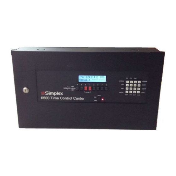
- Page 8 FRONT PANEL DESCRIPTION ALPHANUMERIC DISPLAY - Used for displaying time, day, date, and output status, and for displaying information during programming or reviewing stored programs. In the normal mode of operation, the display will be in the TIME DISPLAY, showing the day, time, and which relays are activated. When programming you can enter the TIME SET, MANUAL CONTROL, and PROGRAMMING MODES from keypad and it is shown on this display.
-
Page 9: Installation
INSTALLATION The 6500 should be securely mounted to a suitable mounting panel or surface according to any local codes using the mounting holes on the back panel. It has a mounting weight of 15 pounds. Be sure the equipment is properly grounded to the facilities ground connection. -
Page 10: The Cursor, Entering Data
The master clock has a feature called Auto Prompt that guides the operator when programming the unit. For the most part the operator merely has to follow the display as the master clock advances through the Program Modes. On a restart (from a “power fail” condition) the master clock will advance through a sequence of all the necessary settings including the Basic Programs. -
Page 11: Entering The Date
two digits for the minutes and press [ENTER]. The cursor will advance to the AM position. Press the AM or PM key then press [ENTER]. Time keeping begins the instant you press [ENTER]. Time can be accurately set to the second by pressing the [ENTER] key at the desired instant. 4.4 ENTERING THE DATE The next entry in the AUTO-PROMPT sequence is entering the date. -
Page 12: Entering Pulse For Relays
for the third, 4 for the fourth or L for the last Sunday. Use the [5] key to enter the L. The change will be made at 02:00 AM on the Sunday you choose. After the Start DST data is entered, the cursor will advance to the Finish DST line. If you have entered a Start DST, you must enter a Finish DST as well. - Page 13 4 are dedicated to secondary clock correction and will no longer be available for timed events. A complete list of clock correction modes supported by the Simplex 6500 will be found in the “Clock Modes Supported” table at the end of this guide. For information on secondary clock modes not described in this guide, please contact JCI Global Fire Detection Technical Support.
-
Page 14: Operation
5.0 OPERATION This section will explain how to change or review the existing time, date or programs previously stored, how or to totally program the unit after exiting the AUTO-PROMPT sequence. It describes how to manually invoke each mode from the command line. You must be in the time display before you can enter a command. Press the [EXIT] key to be sure. -
Page 15: Reviewing Or Editing Day
5.4 REVIEWING OR EDITING THE DAY [4] [ENTER] You must be in the time display. Press the DAY key [4]. The display will respond with: Press [ENTER]. The display will respond with: The day of the week may now be entered in the same manner as in the AUTO-PROMPT sequence. (Section 4.5) 5.4 REVIEWING OR EDITING DAYLIGHT SAVINGS TIME [7] [ENTER]... -
Page 16: Reviewing Or Editing The Relay 2 Pulse
5.6 REVIEWING OR EDITING THE RELAY 2 PULSE (MOMENTARY OUTPUT) [5] [A] [ENTER] To enter the pulse for relay two you must be at the time display. Press [5] [A] [ENTER]. The display will respond with: Once you have entered the pulse for relay 2 (Section 4.8) the master clock will return to the time display. 5.7 REVIEWING OR EDITING THE SECONDARY CLOCK MODE [2] [0] [ENTER]... -
Page 17: Programming
6.1 ENTERING THE BASIC PROGRAM Before you begin programming your 6500 you should complete the MC SERIES PROGRAM RECORD SHEET included at the back of this manual. Be sure to enter pulse lengths if required for all relays (Sections 5.5, 5.6). -
Page 18: Clearing A Program Entry
Entry occurs every Monday Entry occurs every Tuesday Entry occurs every Wednesday Entry occurs every Thursday Entry occurs every Friday Entry occurs every Saturday Entry occurs every Sunday WK0-WK9 Entry occurs on days designated by custom week (see Section 8.1) Hours - Enter the two digit hour at which this entry is to be activated and press [ENTER]. -
Page 19: Entering, Reviewing Or Editing The Annual Program
The display will prompt you for a plan # (cursor on 0). Choose the basic plan in which the entry to be cleared is located, then press [ENTER]. The display will then prompt for a entry # (cursor on 00). Choose the # of the entry to be cleared, then press [ENTER]. -
Page 20: Clearing An Annual Plan
[ENTER] or enter [XX] to repeat the Annual program each year. See the ANNUAL REPEAT PROGRAMS instructions in ADVANCED PROGRAMMING (Section 8.2) for details. The cursor will advance to the end date line. Enter the end date in the same manner as the start date. If your Annual Plan is only for one day, do not enter an end date. -
Page 21: Special Functions
If you wish to clear both the annual and basic programs, repeat the process a second time. Only one can be cleared at a time. 7.0 SPECIAL FUNCTIONS 7.1 MANUAL OPERATION OF THE OUTPUT RELAYS [1] [ENTER] WARNING!! Manually controlling the relays will affect the loads connected to the Master Clock. Operating these loads at the wrong time may cause damage, injury or disruption of activities. -
Page 22: Manual Selection Of Alternate Plans
Circuits (relays) 3 and 4 can be used as regular control circuits if system clocks are not used. If system clocks such as Synchronous Wired clocks are connected, circuits (relays) 3 and 4 are used. See Section 4.9 Entering Secondary Clock Correction Mode. These switches should be in the AUTO position for proper system clock corrections. -
Page 23: Sleep Mode
To exit the Sleep Mode, press [4] [5] [ENTER] again. The 6500 will resume normal operation. During “Sleep Mode” the 6500 ignores all Basic Plan programs (relay outputs are stopped). All other 6500 functions are still available such as entering programs, Changing time or date, manual relay control, etc. Sleep Mode does not affect any stored programs. -
Page 24: Forcing A Restart
6500 can be set for an internal crystal time base. To check or change the time base setting for the 6500 master clock press [3] [0] [ENTER]. The display will read: The cursor will be on the 6. If this is correct for your application press [EXIT]. -
Page 25: Advanced Programming
8.0 ADVANCED PROGRAMMING 8.1 CUSTOM WEEKS (Wk0 – Wk9) [2] [2] [ENTER] Up to ten custom weeks can be user defined for the master clock. This is useful for applications that require the same events on various groups of days of the week. For example: custom week Wk0 could be defined for Mondays, Wednesdays, and Fridays. -
Page 26: Bcd / Ebcd Time Code Output
[2] [4] [ENTER] The 6500 can be set up to transmit 12 or 24 Hour format. Press [2] [4] [ENTER]. The display will show: Press any numerical key to alternate between 12 or 24 Hour mode. One the desired mode is showing, press [ENTER]. - Page 27 Read the sections on Programming Instructions before using the PROGRAMMING SUMMARY. SET TIME - Press TIME [3] key then [ENTER]. Enter the hours, press [ENTER]. Enter the minutes, press [ENTER]. Press [AM] or [PM], press [ENTER]. Timing begins the instant you press [ENTER] on entering the [AM] or [PM].
- Page 28 REVIEWING THE ANNUAL PLAN PROGRAM - Press ANNUAL [A] key then [ENTER]. Press ANNUAL [A] key again repeatedly to review each Annual plan. SETTING THE OUTPUT PULSE – Press [5] then [ENTER]. Enter a pulse length from 1 to 9. Press [ENTER]. Enter the number of the relay(s) the pulse is to be applied to.
- Page 29 6500 SERIES PROGRAM RECORD SHEET LOCATION ___________________________________ DATE ____________________ PULSE LENGTH FOR RELAYS 1,3,4,5,6,7,8 (1-9 SECS) ___ RELAYS PULSED _______________ PULSE LENGTH FOR RELAY 2 (1-9 SECONDS) ___ SECONDARY MODE # ______ (SEE NOTE 1) BASIC PLAN # _____________ NUMBER OF ENTRIES PER PLAN _______...
- Page 30 SIMPLEX 6500 CORRECTION MODES SUPPORTED For information on secondary clock modes not described in this guide, please contact JCI Global Fire Detection Technical Support.
- Page 31 Synchronous Wired LATHEM Type SS Wall Clocks Synchronous Wired NATIONAL E-SRX Series Synchronous Wired RAULAND 2460 Series Synchronous Wired SIMPLEX 77 Series, 2310/6310-91xx and 92xx Synchronous Wired STANDARD Synchronous Wired Synchronous Wired STROMBERG 3000 Synchronous Wired ANNUAL PLAN PROGRAM RECORD SHEET...
- Page 32 * NOTE: TO HAVE ANNUAL PROGRAMS REPEAT EACH YEAR AUTOMATICALLY, PRESS “A” WHEN PROMPTED FOR THE YEAR. THIS WILL INSERT “XX” FOR THE YEAR PORTION OF THE DATE. **** SPECIAL FUNCTIONS **** MANUAL UNIT STATUS PULSE SELECT ALTERNATE PLAN PULSE 2 DEFINE CUSTOM WEEKS MODE SELECT SET PROGRAM SIZE...
- Page 33 Figure 1 115VAC Power Connections Figure 2...
- Page 34 220VAC Power Connections...
- Page 35 Figure 3 Synchronous Wired Clock Connections Figure 4 BCD Connections...
- Page 36 Figure 6 Bell Wiring Connections...
- Page 37 THIS PAGE INTENTIONALLY BLANK SIMPLEX, and the product names listed in this material are marks and/or registered marks. Westminster, MA U.S.A. Unauthorized use is strictly prohibited. Specifications sheets may change without further notice...
Need help?
Do you have a question about the 6500 and is the answer not in the manual?
Questions and answers