Table of Contents
Advertisement
Quick Links
Advertisement
Table of Contents

Subscribe to Our Youtube Channel
Related Manuals for GRT Avionics Mini-X EFIS


Summary of Contents for GRT Avionics Mini-X EFIS
-
Page 1: Mini -X Efis
Mini -X EFIS Installation, Setup, and User Manual Revision A9 14-January-2020... - Page 2 Mini-X Installation, Setup & User Manual GRT Avionics Copyright© 2014 3133 Madison Ave. SE Wyoming, MI 49548 (616) 245-7700 www.grtavionics.com Revision A9...
- Page 3 GRT Avionics Mini-X Installation, Setup & User Manual Mini-X Manual Revision Notes Manual Software Date Change Description Revision Revision 06-Jun-2014 Initial Release Appendix, A.1.5 and A.1.6- Corrected and clarified AHRS and Air Data 16-Jun-2014 Software update instructions. Added & clarified wiring options for Trig TT21/TT22 remote transponder, Section 2.5...
-
Page 4: Warranty & Return Policy
Mini-X Installation, Setup & User Manual GRT Avionics Thank you for choosing GRT Avionics! We hope you enjoy your new avionics system for many years to come. Warranty & Return Policy All GRT products include a 2-year warranty starting on the day the instrument is put into service (or three years after purchase, whichever comes first) against manufacturer defect. -
Page 5: Table Of Contents
Mini-X Installation, Setup & User Manual GRT Avionics Contents Mini -X EFIS .........................1 Warranty & Return Policy........................4 1.1 About the Mini-X........................8 1.2 Tools & References for Installation....................8 1.3 Mini System Requirements......................8 1.4 AHRS Specifications and Limitations..................9 1.5 Basic Controls of the Mini......................11 2.1 Mini-X Connector Definition....................15... - Page 6 Mini-X Installation, Setup & User Manual GRT Avionics 4.2 Explore the Set Menu Pages....................24 4.3 Set Up Your General Preferences...................25 4.4 Set Instrument Orientation.......................26 4.5 External Magnetometer Location Validation ...............27 4.6 Set Final Magnetometer and Instrument Orientation............28 4.7 Fine Magnetometer Calibration Procedure................28 4.8 Altimeter Calibration.......................32...
- Page 7 Mini-X Installation, Setup & User Manual GRT Avionics 6.4 In-Flight Map Setup........................56 6.5 Map Selection Tool........................58 7.1 GPS CDI Bar..........................59 7.2 Flight Planning with the Mini....................59 7.3 Airport/Facilities Information & Radio Tuning.................65 7.4 Synthetic Approach (SAP)......................66 8.1 Autopilot............................68 8.2 Trig TT22 Transponder......................69 8.3 Graphical Engine Monitoring with the EIS................71...
-
Page 8: About The Mini-X
IFR operations. The Mini utilizes the same pilot interface as the popular Horizon and Sport series; If you already use GRT avionics for your primary flight display, you will not have to remember a different brand’s “buttonology” in an IFR emergency. The Mini has a built-in GPS for navigation, so you will always know where you are. -
Page 9: Ahrs Specifications And Limitations
GRT Avionics Mini-X Installation, Setup & User Manual 1.4 AHRS Specifications and Limitations � Maximum Angular Rate: 250 deg/sec � Maximum G-Limit : 4G for unlimited time, 10G for up to 20 seconds. G-limit affects accuracy of the readout, but exceeding it will not damage the instrument. - Page 10 Mini-X Installation, Setup & User Manual GRT Avionics Figure 1-1: Mini Dimensional Drawing (all models) GRT Mini 01-Mar-2014 Notes: � Cutout dimensions 4.15” x 3.30” � Unit is centered within the cutout. � Mounting screws are #4 � Mounting bolt pattern is centered on bezel outline.
-
Page 11: Basic Controls Of The Mini
GRT Avionics Mini-X Installation, Setup & User Manual 1.5 Basic Controls of the Mini The Mini has a single knob that can be pressed and turned, as well as four buttons. The buttons are referred to as “softkeys” because their functions change as screen views and menus change. - Page 12 Mini-X Installation, Setup & User Manual GRT Avionics PFD Level 2 Softkeys (typical) Synthetic Choose Settings Turn to adjust Altimeter Setting More Vision Navigation Main Menu Press for Autopilot items… Display Source Options PFD Level 3 Softkeys (typical) Error or...
- Page 13 GRT Avionics Mini-X Installation, Setup & User Manual 1.5.3 Moving Map Softkey Functions (Optional) 1. Press the MAP softkey to display the Moving Map page. Cycle thru Primary Screen More Turn to adjust map range map views Dimmer Flight items…...
- Page 14 Mini-X Installation, Setup & User Manual GRT Avionics Map Level 3 Softkeys (typical) See objects More Choose Lateral View, Turn to adjust map range off the edge items… Autopilot Create, Edit Press once for Heading Bug of the map Source...
-
Page 15: Mini-X Connector Definition
The colors shown here correspond to the colors in the supplied wiring harness. � The supplied wiring harness for the magnetometer is 20 feet long; all other wires are 4 feet long. � The magnetometer serial output (Mag pin 9) may be shared with other GRT Avionics Mini-EFIS, or the GADAHRS. - Page 16 Mini-X Installation, Setup & User Manual GRT Avionics Figure 2-1: Rear Case View- Connector Placement Pitot Port Static Port GPS Antenna Mini USB Port DB15 Connector (male) Revision A9...
-
Page 17: General Wiring Guidelines
GRT Avionics Mini-X Installation, Setup & User Manual 2.2 General Wiring Guidelines Wires that are certain to be used are pre-installed in the Mini cable assembly connectors. Optional connections to the Mini are not installed in the D-sub connectors at the factory, however, colored aviation-grade wires with pre-installed D-sub connector contacts are included for these connections. -
Page 18: Autopilot Source Switch (Optional)
Mini-X Installation, Setup & User Manual GRT Avionics Power Inputs- The Mini has one power input to be connected to the aircraft’s electrical system, plus an option for an internal backup battery, which is charged through the main power input. -
Page 19: Inter-Display Communication
GRT Avionics Mini-X Installation, Setup & User Manual 2.6 Inter-Display Communication GRT display units communicate between themselves so that most entries made during flight, such as flight plan information, altimeter setting, and screen dimming, can be made from any display unit and will be applied to all. -
Page 20: Trig Tt21/Tt22 Transponder Interface
Mini-X Installation, Setup & User Manual GRT Avionics 2.7 Trig TT21/TT22 Transponder Interface The Mini is able to function as the control head for a Trig TT21 or TT22 remote transponder. Visit the Trig Avionics website for the TT21/22 installation manual and wiring diagrams. -
Page 21: General Serial Port Wiring Information
GRT Avionics Mini-X Installation, Setup & User Manual 2.8 General Serial Port Wiring Information The Mini’s RS-232 serial ports can be used to connect the Mini to a variety of interfacing equipment. In systems using a larger GRT display unit as the primary EFIS, the Mini-X serial ports will most likely be used to connect to the GRT Autopilot servos and the primary GRT EFIS screen for limited data sharing, including flight plans, screen dimming, and altimeter settings. -
Page 22: Placement Of The Mini On The Instrument Panel
Mini-X Installation, Setup & User Manual GRT Avionics Section 3: Mechanical Installation 3.1 Placement of the Mini on the Instrument Panel The Mini is permanently mounted on the instrument panel face. The main consideration in choosing a location is the ability to view the display unit and reach its controls. The Mini includes user settings... -
Page 23: Remote Magnetometer Installation (Optional)
GRT Avionics Mini-X Installation, Setup & User Manual 3.5 Remote Magnetometer Installation (Optional) The remote magnetometer must be placed in an area of the airplane with little or no electromagnetic interference. The cable is 20 feet long and designed to reach out to the wingtip or tail. -
Page 24: Boot-Up Check
Mini-X Installation, Setup & User Manual GRT Avionics Section 4: General Setup and Calibration NOTE: Each subsection in this section represents a step in the setup and calibration of the Mini and optional external magnetometer. Perform each step in the order presented here for the most efficient setup procedure. -
Page 25: Set Up Your General Preferences
GRT Avionics Mini-X Installation, Setup & User Manual 4.3 Set Up Your General Preferences Access the Set Menu > General Setup page. Follow the guidelines below. Scroll down past the serial ports to Page Change. The softkey labels on all PFD and Map pages appear only after a button is pressed, then disappear. -
Page 26: Set Instrument Orientation
Mini-X Installation, Setup & User Manual GRT Avionics 4.4 Set Instrument Orientation This is a coarse setting to account for angled instrument panel installations. You will fine-tune the instrument orientation again in flight after validating the location of the magnetometer (if installed). -
Page 27: External Magnetometer Location Validation
GRT Avionics Mini-X Installation, Setup & User Manual 4.5 External Magnetometer Location Validation Skip to Section 4.8, Altimeter Calibration, if you do not have the optional external remote magnetometer. The internal magnetometer cannot be calibrated. NOTE: When the magnetometer wiring is connected to the designated magnetometer connection pins on the DB15 connector, the Mini will automatically detect it upon boot-up and set up or verify the magnetometer serial port settings. -
Page 28: Set Final Magnetometer And Instrument Orientation
Mini-X Installation, Setup & User Manual GRT Avionics b. With the Magnetometer Calibration page in view, rotate the airplane 360 degrees. A red graph will appear on this page showing the calculated errors. c. If errors of greater than 30 degrees are observed, there is probably a wiring problem. - Page 29 GRT Avionics Mini-X Installation, Setup & User Manual A simple means of pointing the airplane toward magnetic north is to taxi the airplane slowly and use the GPS ground track to determine when you are taxiing in a magnetic north direction.
- Page 30 Mini-X Installation, Setup & User Manual GRT Avionics b. It will exit calibration mode, and will show “Calibration INVALID - Maximum correction exceeded” if a correction of greater than 127 degrees is required. (Invalid - OVERLIMIT will be displayed on the AHRS maintenance page next to the Magnetometer Calibration field.)
- Page 31 Mini-X Installation, Setup & User Manual GRT Avionics the the magnetometer heading. When using the PFD screen, the best technique is to point the airplane in the direction to be tested, wait at least 20 seconds, or until the heading is not changing, and then taxi until the ground track is stable on the PFD also.
-
Page 32: Altimeter Calibration
GRT Avionics Mini-X Installation, Setup & User Manual 4.8 Altimeter Calibration When the Mini is to be used for IFR flight, the altimeter portion of the AHRS must be calibrated to conform to FAR 91.411. This is to be done at an interval in time as dictated by FAR 91.411. It is not necessary to calibrate the altimeter more often than this requirement. -
Page 33: Full Altimeter Calibration - Using Air Data Test Set
Mini-X Installation, Setup & User Manual GRT Avionics 4.9 Full Altimeter Calibration – Using Air Data Test Set This calibration adjusts the relationship between the altitude display and the barometric pressure setting using an Altimeter Test Set. 1. Turn on the Mini and allow at least 5 minutes to elapse before continuing. - Page 34 GRT Avionics Mini-X Installation, Setup & User Manual 10. Set the altimeter test set back to sea level (0 ft') 11. Set the BIAS so that the altimeter reads 0 ft. 12. Complete the calibration by setting the altimeter test set to each altitude listed on the calibration page (5000, 10000, 15000, etc.), and adjusting the corresponding entry until the...
-
Page 35: Airspeed And Wind Calibration
Mini-X Installation, Setup & User Manual GRT Avionics 4.10 Airspeed and Wind Calibration The Mini accurately calculates indicated airspeed via its measurement of the difference between pitot and static pressures. Typical instrument errors are less than 2 mph at 100 mph, and diminish to less than 1 mph at 200 mph. - Page 36 GRT Avionics Mini-X Installation, Setup & User Manual 3. Select a blank table entry in the correction table using the knob. If no entries are blank, then select an entry and press Delete to clear the entry. The START CAL softkey will be displayed when the cursor box is on a blank entry.
-
Page 37: Angle Of Attack (Aoa) Installation And Calibration
Mini-X Installation, Setup & User Manual GRT Avionics 4.11 Angle of Attack (AOA) Installation and Calibration Sensed AOA Installation The sensed version of the angle of attack option uses a two-port pitot tube, such as the Garmin GAP-26 heated pitot probe. If a heated probe is not required, a dual port pitot probe may be fabricated by mounting a second pitot tube, bent downward at approximately a 60 degree angle, as shown here. - Page 38 Mini-X Installation, Setup & User Manual GRT Avionics airplane near stall speed. When performing this step, minimal power should be used, and the flaps should be in the retracted position. Revision A9...
-
Page 39: Primary Flight Display Overview
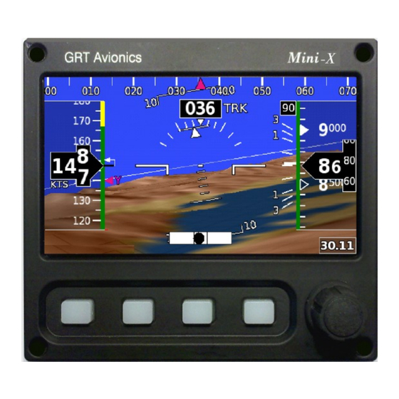
Mini-X Installation, Setup & User Manual GRT Avionics Section 5: Primary Flight Display Screen 5.1 Primary Flight Display Overview Vertical Speed GPS Track Indicator Waypoint Balloon or Heading Lateral Vertical Autopilot Autopilot Annunciators Annunciators Altimeter Airspeed Horizon Line Altimeter Setting... -
Page 40: Airspeed Tape
GRT Avionics Mini-X Installation, Setup & User Manual 5.2 Airspeed Tape The primary function of the airspeed tape is to display indicated airspeed and its associated color bands, all of which are fully programmable according to the aircraft design limitations. It also has several supplemental sources of information to provide the pilot with an intuitive sense of airspeed change, as well as true airspeed and groundspeed. -
Page 41: Altimeter Tape
Mini-X Installation, Setup & User Manual GRT Avionics Customizing the Airspeed Tape For Your Aircraft The airspeed indicator settings are programmed in Set Menu > General Setup > Primary Flight Display. They should be programmed before the first flight according to the design limitations of the aircraft and can be fine tuned during flight testing to match the individual aircraft’s flight... - Page 42 GRT Avionics Mini-X Installation, Setup & User Manual Altitude Bug The selected altitude is displayed in the Altitude Preselect Window located above the altimeter tape and is marked on the altimeter tape itself by a magenta rectangle “bug” with a notch. The altitude bug serves two functions: �...
-
Page 43: Vertical Speed Indicator
Mini-X Installation, Setup & User Manual GRT Avionics 5.4 Vertical Speed Indicator The vertical speed indicator (VSI) is along the left side of the digital altimeter. The tape is white and radiates upward or downward from value the neutral mark as the aircraft climbs and descends. It shows vertical speed in feet or meters per minute. - Page 44 GRT Avionics Mini-X Installation, Setup & User Manual Using the Heading Bug Heading/Track NOTE: If Track (TRK) is being used as the Heading reference, the Heading Select Window and Heading Bug will refer to GPS track, not magnetic heading. To change the position of the heading bug from the PFD screen: 1.
-
Page 45: Attitude Indicator/Artificial Horizon
Mini-X Installation, Setup & User Manual GRT Avionics 5.6 Attitude Indicator/Artificial Horizon The Artificial Horizon is just that, a pictorial representation of the earth. The blue portion represents the sky; the green or brown portion represents the ground. The Mini-X displays a computer generated representation of the “view out the window”... - Page 46 GRT Avionics Mini-X Installation, Setup & User Manual Adjusting Pitch Ladder Offset During straight and level unaccelerated flight at the normal cruise power setting, the pitch ladder should be set so that the Attitude Reference Index is aligned with the zero-pitch line. The object is to set the pitch ladder for the easiest possible instrument scan during cruise.
-
Page 47: Flight Path Marker
Mini-X Installation, Setup & User Manual GRT Avionics Slip/Skid Inclinometer The electronic slip/skid “ball,” or inclinometer, works using the internal accelerometers in the AHRS. It can be turned off for decluttering purposes. To turn it on or off: Access the Set Menu > Primary Flight Display page. - Page 48 GRT Avionics Mini-X Installation, Setup & User Manual G-Meter Activation & Display 1. Access the Set Menu > Primary Flight Display page. 2. Scroll to the G-Meter options near the bottom of the screen. Select an option on the G-Meter Mode setting: a.
- Page 49 Mini-X Installation, Setup & User Manual GRT Avionics 5.9 Synthetic Vision Features & Settings Synthetic vision (SV) is standard on the Mini-X. It displays a 10-mile “out the window” view on the PFD of terrain, runways, and obstacles. GRT factory technicians load the synthetic vision terrain database appropriate for the area of the world in which each Mini will be used prior to shipment.
- Page 50 GRT Avionics Mini-X Installation, Setup & User Manual 5.9.2 Obstacles Towers and other obstacles in the 56-day Navigation Database are displayed on the PFD as either simple lines or chart-style graphic tower symbols. The same altitude color-coding as Terrain applies.
- Page 51 Mini-X Installation, Setup & User Manual GRT Avionics 5.9.5 Waypoint Balloons Waypoint balloons are markers that highlight the next GPS waypoints in the flight plan on the PFD. They have a “tether” that points directly downward to the waypoint and are raised and lowered with the altitude bug.
-
Page 52: Enroute Hits
Mini-X Installation, Setup & User Manual GRT Avionics 5.9.7 Enroute HITS Enroute HITS (Highway-In-The-Sky) is a series of boxes drawn along a Sequence Mode GPS flight plan. The boxes move up and down according to the altitude bug, forming a visual corridor that is centered on the set course and altitude. -
Page 53: Moving Map Overview
Mini-X Installation, Setup & User Manual GRT Avionics Section 6: Optional Moving Map & HSI 6.1 Moving Map Overview When equipped with the optional Moving Map/HSI software, the Mini features a set of moving map screens, including an HSI to assist with GPS navigation and VOR/LOC tracking if a nav radio is connected. -
Page 54: Moving Map Database
GRT Avionics Mini-X Installation, Setup & User Manual 6.2 Moving Map Database The moving map is derived from the internal synthetic vision terrain database, the GRT cities/water/railroads/roads/state boundaries database, and the Navigation Database. The Navigation Database should be updated every 56 days. A free version is available from the GRT website (continental U.S. - Page 55 Mini-X Installation, Setup & User Manual GRT Avionics 6.3.3 Map Screen Declutter Settings In some areas, there are so many airports, fixes, and navaids that the map gets cluttered up with information. The Mini has settings to relieve the congestion on the map automatically.
-
Page 56: In-Flight Map Setup
GRT Avionics Mini-X Installation, Setup & User Manual 6.4 In-Flight Map Setup From the Map screen, press NEXT to access the softkeys shown below. 6.4.1 Compass Rose Display Options Press the MAP softkey repeatedly to cycle through the different map display options. - Page 57 Mini-X Installation, Setup & User Manual GRT Avionics 6.4.3 Map Background Options The SHOW softkey lets the pilot choose one of several mapping data sets to display on the map. SHADE- Displays topography shading similar to that shown on a VFR Sectional chart. The data is derived from the internal synthetic vision database.
-
Page 58: Map Selection Tool
GRT Avionics Mini-X Installation, Setup & User Manual 6.5 Map Selection Tool The yellow Map Selection Tool cursor can be used to: � Select and go direct to a waypoint � Access the Waypoint Information Page � View airport information and airspace dimensions A data box appears above the knob that displays important information for map features highlighted by the yellow Map Selection Tool cursor. -
Page 59: Gps Cdi Bar
Mini-X Installation, Setup & User Manual GRT Avionics Section 7: Flight Planning & Navigation 7.1 GPS CDI Bar The GPS CDI (Course Deviation Indicator) is located at the bottom center of the screen. It displays the distance from the aircraft’s current position to the course line connecting the previous and next waypoint in the GPS flight plan. - Page 60 GRT Avionics Mini-X Installation, Setup & User Manual 7.2.1 To Go Direct to Nearest Airport or Navaid: 1. Press FLIGHT PLAN softkey to bring up the Active Flight Plan page. 2. Press Mode softkey. 3. Press NEAR softkey, then press AIRPORT or NAVAID to bring up a list of nearest waypoints.
- Page 61 Mini-X Installation, Setup & User Manual GRT Avionics 7.2.2 To Enter a Direct-To Waypoint: 1. Press FLIGHT PLAN softkey to bring up the Flight Plan Entry Page. 2. Press the Mode softkey. A page appears with columns of letters and numbers, shown below.
- Page 62 GRT Avionics Mini-X Installation, Setup & User Manual 7.2.3 To Enter a Multiple-Waypoint Internal Flight Plan 1. Press FLIGHT PLAN softkey to bring up the Flight Plan Entry Page. 2. To add a new waypoint, press the ADD softkey. The waypoint entry page will appear. Follow steps 3-5 outlined in the Entering a Direct-To Waypoint section to enter the first waypoint.
- Page 63 Mini-X Installation, Setup & User Manual GRT Avionics 7.2.4 Using an External Flight Plan External Flight Plans, highlighted by a yellow header strip, are read directly from a connected external GPS. They can be followed, but not edited, by the Mini.
- Page 64 GRT Avionics Mini-X Installation, Setup & User Manual 7.2.5 Importing a .GPX Flight Plan Many apps and GPS units create and store flight plans in .GPX format. The Mini, like the bigger GRT EFIS systems, can read .GPX files placed onto the USB stick.
-
Page 65: Airport/Facilities Information & Radio Tuning
Mini-X Installation, Setup & User Manual GRT Avionics 7.3 Airport/Facilities Information & Radio Tuning Information about airports and navaids in the navigation database is available on the Mini on the Details page. Select the airport or navaid from the Active Flight Plan page. -
Page 66: Synthetic Approach (Sap)
Mini-X Installation, Setup & User Manual GRT Avionics 7.4 Synthetic Approach (SAP) The Mini-X has the capability to draw a synthetic approach path to any runway in the navigation database. The approach path is marked by Highway- In-The-Sky boxes (also known as HITS) - Page 67 Mini-X Installation, Setup & User Manual GRT Avionics 2. Fly toward the airport in HDG mode if you are following ATC vectors or if you are not approaching the desired runway at a natural intercept angle. The autopilot will perform a simple turn onto the SAP when it captures the final approach course.
-
Page 68: Autopilot
GRT Avionics Mini-X Installation, Setup & User Manual Section 8: Miscellaneous Features 8.1 Autopilot When the aircraft is equipped with GRT autopilot servos, the Mini-X is a self-contained 1- or 2-axis autopilot. It provides the following controls based on internal AHRS, GPS course, and optional VHF... -
Page 69: Trig Tt22 Transponder
Mini-X Installation, Setup & User Manual GRT Avionics 8.2 Trig TT22 Transponder The Mini can act as the control head for a Trig TT21 or TT22 Remote Transponder. See Section 2.7 of this manual for wiring information. 8.1.1 Activating TT22 Setup on the Mini 1. - Page 70 GRT Avionics Mini-X Installation, Setup & User Manual 8.2.3 Transponder Mode/Code Display Once the TT22 A/B port or serial port is set up, there is a Transponder display box in the lower left hand corner of the EFIS screen under the airspeed tape. This box shows the active mode and squawk code.
-
Page 71: Graphical Engine Monitoring With The Eis
In addition to the typical engine monitoring functions, the EFIS includes several engine monitoring functions that are unique to GRT Avionics. These are based on our extensive experience in this area. They are described in the following sections. - Page 72 Mini-X Installation, Setup & User Manual GRT Avionics Engine Display Breakdown Fuel & Environmental Main Dials Group Graphs Variable Group Softkey to Cycle) (Press DATA Revision A9...
- Page 73 Mini-X Installation, Setup & User Manual GRT Avionics Engine Display Pages Six full-screen pages are provided. The content of the lower-right portion of the screen varies, as described below, according to the intended use. Selection of the engine page is made on the second set of softkey pages. Pressing any key will display softkey labels and pressing the “NEXT”...
- Page 74 Mini-X Installation, Setup & User Manual GRT Avionics Exhaust Gas Temperatures Engine Page This page features a prominent EGT time history graph and the traditional EGT bar graph. The knob allows you to review the last 10 minutes of the line graph. The size...
- Page 75 Statistics Engine Page This page provides information, some of it exclusive to GRT Avionics, that is perfect for evaluating efficiency–especially during cruise. Featured on this page is “Specific Fuel Consumption” (read more about it below), as well as miles per gallon over the ground.
- Page 76 EGT increases by as much as 50°. In short, EGT/CHT time histories (exclusive to GRT Avionics) are the only practical way to detect a large variety of developing engine problems.
- Page 77 Mini-X Installation, Setup & User Manual GRT Avionics CHT/EGT Time History Display The EGT and CHT time history graphs are only viewable on the History Engine Page. The graphs show a two-minute window. The right side of the graph represents the current time. The last 10 minutes of history may be reviewed by turning the knob.
- Page 78 Mini-X Installation, Setup & User Manual GRT Avionics In this screen shot, all EGTs changed abruptly about 1 minute ago. This was likely caused by pilot action, such as leaning, but if no intentional changes to the engine were made, it could represent the failure of a magneto.
- Page 79 Mini-X Installation, Setup & User Manual GRT Avionics The alarm function may also be used routinely in cruise flight to give you early warning of unusual conditions. Limits can be established based on experience, but 50°F is a good starting point.
- Page 80 Mini-X Installation, Setup & User Manual GRT Avionics Fuel Flow The accuracy of the Fuel Remaining Estimate (Totalizer) derived from the fuel flow sensor is a valuable function for any pilot who uses their airplane for cross-country flights. It is also essential when you’ll be using most of the airplane’s fuel capacity.
- Page 81 Mini-X Installation, Setup & User Manual GRT Avionics Resetting the Totalizer After Adding Fuel The totalizer can be updated on the EIS engine monitor or the EFIS display unit. If the EIS is mounted in the instrument panel, it should be used. This allows both the EIS and EFIS to provide totalizer data.
- Page 82 Engine Efficiency Measurement Using SFC Specific Fuel Consumption (SFC) is a direct indicator of engine efficiency. This GRT Avionics- exclusive, continuously computed feature is ideal for verifying proper leaning and indicates when you need to lean again.
- Page 83 Mini-X Installation, Setup & User Manual GRT Avionics Verifying Proper Leaning Using SFC After power has been set and the engine leaned as desired, the SFC should be reviewed. Efficient leaning should result in an SFC of close to 0.40 for a piston engine. Leaning to a richer-than-max efficiency will result in a slightly higher value.
- Page 84 Mini-X Installation, Setup & User Manual GRT Avionics Entry of the Power Setting Table 1. Press NEXT > Set Menu > Engine Limits. 2. Scroll to Engine Performance and press the knob to access the Engine Performance table. An example for a 180-horsepower Lycoming is shown below.
-
Page 85: Data Recording
Mini-X Installation, Setup & User Manual GRT Avionics 8.4 Data Recording There are three basic types of files that you can record off the Mini: � A simple “snapshot” is a still shot of the screen. This is saved as a PNG file on your USB drive. - Page 86 GRT Avionics Mini-X Installation, Setup & User Manual 8.4.2 Demo Recordings Demo recordings can be recorded on a one-by-one manual basis or you can set up your Mini to automatically record every flight. Files are not overwritten, so eventually you will need to either erase the USB stick or install a new one.
- Page 87 Mini-X Installation, Setup & User Manual GRT Avionics Dump demo data into a spreadsheet: Download the GRT DECODE program from the GRT Avionics website (Support > Software Updates > Miscellaneous Software & Utilities). Open the program and use it to open the demo file. It will create a spreadsheet with all of the data points.
- Page 88 Mini-X Installation, Setup & User Manual GRT Avionics 8.5 Angle of Attack (not in v32a software) Angle-of-attack (AOA) refers to the angle of the local airflow relative to the wing. Since the wing will stall when the “critical” angle of attack is exceeded, AOA is useful for stall warning, and as a means of establishing an approach speed that accounts for the current weight of the airplane.
- Page 89 Mini-X Installation, Setup & User Manual GRT Avionics The indexer will show a green circle, with no chevrons, when the angle-of-attack is in the optimal range. When the AOA data used to drive the EFIS screens is based on the “calculated” AOA data, “EST”...
- Page 90 Mini-X Installation, Setup & User Manual GRT Avionics 8.5.3 Pitch Limit Indicator When enabled on the PFD settings page, the pitch limit indicator appears on the PFD screen when the angle-of-attack is less than 8 degrees from stall, and goes away when the angle of attack more than 9 degrees from stall.
-
Page 91: Updating Mini Software
AHRS, and all interfacing third party equipment, especially navigation equipment. A.1.1 Locate the New Software on the GRT Website 1. Go to the GRT Avionics website: www.grtavionics.com. 2. Under the Support menu, click on Software Updates to take you to the Software main page, or select directly from the popup list to access the website page dedicated to your EFIS system software. - Page 92 Mini-X Installation, Setup & User Manual GRT Avionics 1. Insert the USB drive into the computer’s USB port. A window may pop up that says “Auto Play.” This window will also list the USB drive’s name as “Removable Disk” with a letter designation.
- Page 93 GRT Avionics Mini-X Installation, Setup & User Manual A.1.4 Load New Navigation Database 1. Press the SET MENU softkey. Turn the knob to scroll to “Display Unit Maintenance.” Press the knob to select. 2. Scroll to “Database Maintenance” and press the knob to open the page.
-
Page 94: Backup Battery Operation
Mini-X Installation, Setup & User Manual GRT Avionics A.2 Backup Battery Operation The backup battery option allows the Mini to operate from an internal user-replaceable Li-ion battery when external power is lost. The battery is charged automatically when the instrument is provided with aircraft power. - Page 95 Mini-X Installation, Setup & User Manual GRT Avionics Battery Capacity Re-calibration Beginning with Mini software version 2, there is a battery capacity re-calibration procedure that can be done during annual maintenance. This will re-calibrate the battery meter so that its estimate of the capacity remaining is more accuate.
- Page 96 Mini-X Installation, Setup & User Manual GRT Avionics Revision A9...
Need help?
Do you have a question about the Mini-X EFIS and is the answer not in the manual?
Questions and answers