
Related Manuals for Giant Leap Rocketry Talon 2


Summary of Contents for Giant Leap Rocketry Talon 2
- Page 1 INSTRUCTION MANUAL Talon 2 GIANT LEAP ROCKETRY, LLC Copyright 2006 - 2017 Giant Leap Rocketry, LLC 2831 SW Cornelius Pass Road Hillsboro, Oregon 97123...
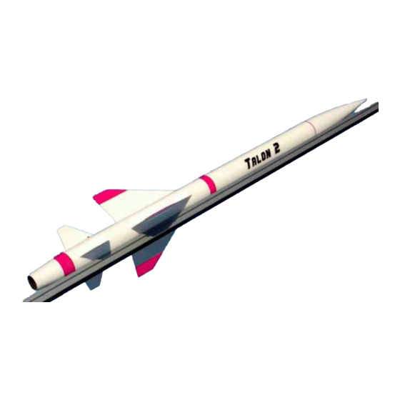
- Page 2 We at Giant Leap Rocketry, LLC hope you enjoy building the best looking and best flying rocket on the flying field. The Talon 2 is stylish and commands attention wherever you fly. It flies with 29mm motors as small as the Aerotech F50, or as large as the I200.
- Page 3 Aerotech F50 to as larges as an WARNING!! I200. These will propel the TALON 2™ to ex- tremely high altitudes. Flying rockets is potentially dangerous, and Specifications you or others can be injured and/or killed by the usage of this product.
-
Page 4: Parts List
Leap Rocketry for a refund. By using this kit, NENT SAFETY CODES AND DIREC- you agree that you have read, understand and TIONS AT THE LAUNCH SITE. ALWAYS accept these conditions. WEAR EYE PROTECTION WHENEVER LOADING EJECTION CHARGES OF PLEASE READ THE SAFETY CODE AND ANY TYPE AND KEEP SPECTATORS LIABILITY STATEMENTS AT THE END AWAY. - Page 5 2- 54mm/29mm Centering Rings 3- Small 0.063” Fiberglass Pre-cut Fins 3- Large 0.063” Fiberglass Pre-cut Fins 1- 29mm Original GLR Slimline Retainer Set 1- 54mm Original GLR Rail Guide Pair Recovery Mount: 1- 54mm Original GLR Hardpoint Recovery System Anchor Which Includes: 1- 54mm GLR Hardpoint Anchor Online Assembly Instruction Booklet 1- 1 ½”...
- Page 6 Rubbing Alcohol line Motor Retainer. Sand the motor tube Drill with a /32” drill bit slightly, if necessary, but just enough for a NOTE: you MUST use high-quality epoxy and snug-tight fit. If you have a 29mm casing (Ae- JB Weld with this kit. Other types of adhesives rotech or Pro29), test fit it by placing the casing are not suitable and will make the rocket unsafe in the motor tube and inserting the retaining...
- Page 7 installing it in pletely. order to spread Place the Middle Cen- the J.B. Weld. tering Ring onto the mo- Be sure that tor tube. Measure from you only apply the Aft end of the motor the J.B. Weld tube (the end with the to the motor GLR Slimline Retainer tube and NOT...
- Page 8 GLR Pinnacle Tailcone. Each air- to the Airframe. Fillets can be created using a frame and GLR Pinnacle Tail- variety of materials, Giant Leap Rocketry, LLC cone are paired and cut together. You will notice as you put the GLR Pinnacle Tailcone and air- frame together there is a mark on each piece.
- Page 9 which each set of fin slots were prepared and assembly and line it up correctly. The Middle you must maintain this position if your fins are Centering Ring will be Forward of the small fin to line up true to one another. slots and the Forward Centering Ring will be Forward of the large fin slots.
- Page 10 Once you have a good thick coating of JB Weld FRAME. Take care to remove the paper towel circumferentially at this location insert the mo- or masking tape from the GLR Slimline Motor tor tube the rest of the way until the motor tube Retainer and clean the GLR Slimline Motor Re- is inserted correctly and the Centering Rings tainer with a solvent to insure that no JB Weld...
- Page 11 As de- scribed earlier, fillets can be created using a va- Install the GLR Hardpoint Recovery Sys- riety of materials, Giant Leap Rocketry, LLC tem Anchor. recommends using GLR Aeropoxy and GLR The GLR Hardpoint Recovery System Anchor Glass-Micro-Spheres.
- Page 12 Rest assured the GLR Hardpont will bring your The GLR Hardpoint is now Talan 2 ™ home! ready to be inserted into the airframe and test fit it. Hold Scuff sand the outer diameter of the GLR Hard- the GLR Kevlar® shock point in a circumferential direction to give the cord and slide the GLR adhesive a better “bite”.
- Page 13 long use of your rocket. The purpose of this small piece of GLR Kevlar® Sock is to prevent potential damage to the GLR Kevlar® shock cords during deployment of the recovery sys- tems. When the recovery system deploys, the GLR Kevlar® Shock Cords will rub against the sharp edge of the phenolic airframe and theoreti- cly could wear the GLR Kevlar®...
- Page 14 don't scrimp. You want the GLR Hardpoint se- let the GLR Kevlar® Parachute Heat Shield curely attached to the airframe. Hold the Kev- slide freely. lar® shock cord and slide the GLR Hardpoint Attach the eye bolt to the Aft end of the into the airframe and allow it to slide all the GLR Pinnacle Nosecone as shown in the photo.
- Page 15 its poly bag and hold it by the evened out about 3-4" long, then insert it into the tube. shroud lines. - 10’ from the airframe. When the Leave some of the cord out. rocket descends you don’t want the airframes 2.
- Page 16 gently with 240 grit sandpaper. Remember, the and the other about 24" forward from the aft chute is deployed when HOT gases from ejec- end of the rocket. Then trace each GLR Rail tion charge expand in the airframe, popping the Guide on the airframe.
- Page 17 Safety Code and Waiver must be sanded away. That said, the material does Giant Leap Rocketry, LLC (herein referred to shrink a bit as it drys, so it as GLR) has exercised reasonable care in the must be left a little high.
- Page 18 quential damages, even if GLR has been ad- encountered in flight. 6. A high power rocket vised of the possibility of such damages, or for vehicle intended to be propelled by one or more any claim by another party. Lack of care can be high power solid propellant rocket motor(s) dangerous.
- Page 19 a payload that is intended to be flammable, ex- ond following ignition system activation. 12.4 plosive, or cause harm. 10.2 Do not fly a verte- Install an ignition device in a high power rocket brate animal in a high power rocker. motor only at the launch site and at the last prac- Launching Devices 11.1 Launch from a stable tical moment before the rocket is placed on the...
- Page 20 in Table 2 of the Tripoli Safety code. See risks, (b) that even by observing the above pro- www.tripoli.org <http://www.tripoli.org/> . 16. cedures there remain RISKS OF INJURY OR Launch Operations. 16.1 Do not ignite and DEATH from HIGH POWER ROCKETRY, (c) launch a high power rocket horizontally, at a tar- that the utmost in attention and prudence must get, or so the rocket's flight path goes into...
Need help?
Do you have a question about the Talon 2 and is the answer not in the manual?
Questions and answers