Table of Contents
Advertisement
Quick Links
Model 580A
Two Channel Control Module
Combustible Gas Applications
The information and technical data disclosed in
this document may be used and disseminated
only for the purposes and to the extent
specifically authorized in writing by General
Monitors.
Instruction Manual
General Monitors reserves the right to change
published specifications and designs without
prior notice.
Part No.
Revision
MAN580A
MAN580A
B/11-22-04
Advertisement
Table of Contents
Troubleshooting

Related Manuals for General Monitors 580A


Summary of Contents for General Monitors 580A
- Page 1 General Monitors. Instruction Manual General Monitors reserves the right to change published specifications and designs without prior notice. MAN580A Part No.
- Page 2 Model 580A This page intentionally left blank.
-
Page 3: Table Of Contents
INTRODUCTION .......................... 1 Protection for Life............................ 1 Special Warning............................1 Customer Support ........................2 1.0 BEFORE INSTALLATION...................... 3 Differences Between Models 580A and 580 ................3 General Product Description ..................... 3 Controller ........................... 4 Sensor Assembly........................5 2.0 INSTALLATION........................6 Location of the Controller ...................... - Page 4 5.0 TROUBLESHOOTING......................26 General ............................ 26 Troubleshooting Table......................26 Fault Codes ..........................27 6.0 CUSTOMER SUPPORT ....................... 28 General Monitors’ Offices ......................28 Other Sources of Help ......................28 7.0 APPENDIX..........................29 Warranty ..........................29 General Specifications - Controller..................30 7.2.1...
-
Page 5: Illustrations
Model 580A Illustrations Figure 1: Model 580A Controller ..........................4 Figure 2: Schematic Battery Backup System.......................7 Figure 3: Rear Terminal Connections (REF: 20659) ...................8 Figure 4: Junction Box Assembly – Sensor .......................12 Figure 5: Protection Circuit for Relay Contacts....................14 Figure 6: Front Panel Display..........................15 Figure 7: Portable Purge Calibrator ........................17... - Page 6 Table 7: Setup Display Options .........................23 Table 8: Troubleshooting Table .........................27 Table 9: Maximum Cable Lengths ........................31 Table 10: GMI Sensors Available for 580A System...................31 Table 11: Recommended Spare Parts.......................33 Table 12: Calibration Schedule..........................34 Table 13: Product Configuration Table ......................35...
-
Page 7: Introduction
Special care must be taken when wiring the system, to ensure that only the connection points are touched. Only catalytic bead sensors designed by General Monitors will work with the Model 580A Controller. Any attempt to use a sensor that has not been approved by General Monitors, will void the warranty. -
Page 8: Customer Support
Sensors are designed with sintered metal, or screen covers, that act as flame arrestors. Do not operate sensors without screen or sintered metal parts in place. General Monitors’ gas detection systems are primarily safety devices for the protection of personnel and facilities and must be “always ready”. With proper installation, calibration, and maintenance, the system provides continuous monitoring of hazardous areas. -
Page 9: Before Installation
They must be connected to the controller in accordance with the installation instructions in this manual. NOTE: The 580A is different than its predecessor the 580. The 580A calibration is automatic where the 580 must be manually calibrated. Please check the individual manuals for details about wiring, set up and operation of these two units. -
Page 10: Controller
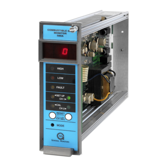
Model 580A CAUTION: The Model 580A Controller is easy to install and operate. However, one should fully read and understand this manual before attempting to place the system in service. Figure 1: Model 580A Controller Controller The Model 580A Controller is a two-channel system where the controller continuously monitors the inputs of two sensors. -
Page 11: Sensor Assembly
Set points for High and Low alarms are adjustable from 5 to 60% LEL. NOTE: A service-loop is necessary between the Model 580A Controller’s rear panel terminals and field/power wiring. This service loop permits the controller to be removed or slid forward for servicing. This service loop is a definite advantage when replacing or changing a controller. -
Page 12: Installation
Model 580A 2.0 Installation Location of the Controller The Model 580A Controller should be installed in a weather-protected, non-hazardous area. The following mounting hardware is available to facilitate installation: Part Description Part Number 102mm (4”) panel mount frame P/N 10199-1 483 mm (19”) rack frame (4 controllers) -
Page 13: Battery Backup
An emergency battery backup may be employed on a system normally powered by AC. A Model 580A Controller requires approximately 2 ampere (peak) at 24 VDC. The battery rating (ampere-hour capacity) is dictated by the length of time power outages may last. -
Page 14: Figure 3: Rear Terminal Connections (Ref: 20659)
Model 580A Figure 3: Rear Terminal Connections (REF: 20659) -
Page 15: Remote Reset Connection
Several variables are involved in selecting locations to install sensors. There are no hard and fast rules defining the optimum location. However, the following general suggestions should be considered with regard to particular conditions at the site where a Model 580A Controller is being installed. -
Page 16: Sensor Installation
Second, many paints contain lead, which can poison a sensor. Sensor Installation Various types of sensors can be provided with the Model 580A Controller. However, the installation method is identical in all cases. Please refer to Section 7.6 for further information. -
Page 17: Table 2: Terminal Colors
Model 580A Sensor cable connections must be crimped and SOLDERED for stable operation. Use only continuous, un-spliced cable runs if possible. Improperly spliced cable can result in corrosion, resistance changes, and drift. To connect the cable at the sensor: 1. Remove the P/N 10252-1 housing lid to reveal the terminal strip. The sensor is connected in the housing according to the color designations (Figure 3). -
Page 18: Figure 4: Junction Box Assembly - Sensor
Model 580A Figure 4: Junction Box Assembly – Sensor... -
Page 19: Alarm Wiring Connections
Model 580A SENSOR GUARDS PART NUMBER DESCRIPTION 1800822 DUST GUARD 10395-1 SPLASH GUARD 10110-1 DUST GUARD WITH DISPOSABLE SCREEN Table 4: Sensor Guards CAUTION: Always mount sensors pointing downward, so that water does not accumulate on the sensor head. Mounting must be as free from shock and vibration as possible, and should be convenient for calibration checks in place. -
Page 20: Figure 5: Protection Circuit For Relay Contacts
Model 580A Caution: Inductive loads, such as bells, buzzers, relays, contactors, solenoid valves, etc., connected to the High alarm, Low alarm and Fault alarm relays must be clamped down as shown in the diagrams below. Unclamped inductive loads can generate voltage spikes in excess of 1000 Volts. Spikes of this magnitude will cause false alarms and possible damage. -
Page 21: Start-Up And Operation
3.0 Start-Up and Operation Types of User Interfaces User interfaces are provided so that the operator may interpret and direct the Model 580A in the performance of its various functions. User interfaces consist of a digital display, status indicators, a channel/select button, a mode button, and a reset button. -
Page 22: Initial Application Of Power
Model 580A NOTE: If one channel is in fault, and the other is in alarm, the gas reading of the alarmed channel displays. The error code of the channel in fault is shown after the alarm condition is removed. NOTE: If one channel is in fault, and the other channel’s gas reading is below alarm level, the fault error code displays. -
Page 23: Calibration Check Mode
Model 580A NOTE: A channel’s sensor detects a gas concentration in excess of an alarm set point. The associated alarm outputs will activate. After a few moments, the gas concentration drops below the alarm set point. If the alarm outputs are latched, the operator can press the Reset button and the latched alarm outputs will return to their normal (safe) state. -
Page 24: Calibration Mode
Calibration Mode NOTE: For better results power up the sensor at least an hour before calibration. To calibrate the Model 580A: 1. Make sure the calibration gas is the same concentration as the user specified calibration level. -
Page 25: Aborting Calibration
Model 580A 7. Remove the gas by closing the valve on the cylinder and taking the calibration cap off the sensor. Watch the display return to normal operation, when the gas concentration drops below 5% LEL. 8. Repeat steps 1-7 for the other channel. -
Page 26: Entering The Password
Model 580A NOTE: Before entering the Setup mode to make changes, the user should fill out the Setup Mode Selection Table (Section 3.9). This aids the user during the selection process in the Setup mode. The Password, the High & Low Alarm set points and the Calibration Level options offer the operator more than two choices. -
Page 27: Low Alarm Options
Model 580A The last High alarm option to appear on the display is the alarm set point (trip level). If this level is reached or exceeded, the High alarm outputs activate. The display indicates the current High alarm set point (5 to 60 in increments of 5). Press the Mode button repeatedly, until the desired high alarm set point appears on the display. - Page 28 Model 580A Press the Mode button repeatedly; until the desired value displays, the unit then executes the Setup Check mode and then returns to normal operation.
-
Page 29: Setup Mode Selection Table
Model 580A. The table shown below indicates the order of options in the Setup mode. To the right of the option entry is a description of the choices that are available for that option. -
Page 30: Check Points For Calibration And Operation
Model 580A Check Points for Calibration and Operation 3.9.1 Frequency of Calibration It is very important that the owner/operator of this equipment determine the correct calibration schedule for their particular environment. The frequency of calibration may be substantially shorter then 90 days depending on environmental contaminants and conditions. -
Page 31: Maintenance
4.0 Maintenance General maintenance Once installed, the Model 580A Controller requires little or no routine maintenance, other than periodic calibration checks. GMI recommends that a calibration schedule be established and adhered to. GMI also recommends that a logbook be kept, showing calibration dates and dates of sensor replacement. -
Page 32: Troubleshooting
If equipment or qualified personnel required for various tests is not available, it is recommended that the defective unit be returned to General Monitors for repair. A complete written description of the problem should be included. -
Page 33: Fault Codes
Model 580A Fault Codes In addition to the Fault LED on the front panel, the Model 580A provides a Fault Code on the digital display whenever a fault condition occurs. The Fault Codes that can appear on the digital display are... -
Page 34: Customer Support
Email: gmme@emirates.net.ae United Arab Emirates Other Sources of Help General Monitors provides extensive documentation, white papers and product literature for its complete selection of safety products. A selection of these documents are available online at the General Monitors website at http://www.generalmonitors.com. -
Page 35: Appendix
7.0 Appendix Warranty General Monitors warrants the Model 580A Controller to be free from defects in workmanship or material under normal use and service, within two (2) years from the date of shipment. General Monitors will repair or replace, without charge, any such defective equipment found to be defective during the warranty period. -
Page 36: General Specifications - Controller
Model 580A General Specifications - Controller 7.2.1 Mechanical Specifications Dimensions: 2.1”W x 6.9”H x 11.5”D (53mm x 175mm x 292mm) Weight: 3.8 lbs. (1.8 kg) Mounting Configuration: Rack, panel, wall 7.2.2 Environmental Specifications Temperature Range: 32°F to 140°F (0°C to 60°C) Storage Temperature: -4°F to +149°F (-20°C to 65°C) -
Page 37: Cable Requirements
4800 2320 7600 Table 9: Maximum Cable Lengths Sensors The following is a list of GMI sensors available for use with the Model 580A Controller: PART NUMBER DESCRIPTION 10001-1 Standard Industrial Combustible Gas Sensor. Used for most hydrocarbons and hydrogen. Temperature range –65°F to +200°F (-55°C to +93°C). -
Page 38: Accessories
Model 580A Accessories 7.6.1 Calibration Equipment Calibration accessories may be purchased from GMI. Contact the factory, or your local representative, for technical or ordering information. The Portable Calibration Chamber is used to calibrate sensors for any specific combustible vapor, which has a flash point below ambient temperature. The customer must provide his own sample of the liquid to use with the chamber. -
Page 39: Recommended Spare Parts
7.6.2.4 Sensor Flow Chamber (P/N 10066) The General Monitors’ Sensor Flow Chamber is constructed of aluminum (optional stainless steel construction available). The chamber has an internal thread into which a sensor may be screwed, and two threaded ports, which accept ¼... -
Page 40: Sample Calibration Schedule And Checklist
Model 580A Sample Calibration Schedule and Checklist To perform a Calibration Check or Calibration, refer to Sections 3.4 and 3.5. Sensor Serial Number Location ___________________ _____________________ 1. Installation and Preliminary calibration. Date: __________________ Record date after preliminary calibration is done. -
Page 41: Product Configuration Table
Model 580A Product Configuration Table MODEL 580A TWO CHANNEL COMBUSTIBLE GAS CONTROLLER A. CONTROLLER 580A Model 580A Controller 3.0 lbs. 1 (Std) -P1 110VAC/24VDC - P2 220 VAC/24 VDC RELAY – STATE (STD) RS 1 LATCH ALARM NON-LATCH WARN DE-ENERGIZED... -
Page 42: Engineering Documentation
Model 580A 7.10 Engineering Documentation 7.10.1 Panel Assembly, Panel Mount – 98, Ref: 10199C Figure 8: Panel Assembly, Panel Mount –98, Ref: 1019... - Page 43 ADDENDUM Product Disposal Considerations This product may contain hazardous and/or toxic substances. EU Member states shall dispose according to WEEE regulations. For further General Monitors’ product WEEE disposal information please visit: www.generalmonitors.com/customer_support/faq_general.html All other countries or states: please dispose of in accordance with existing federal, state and local...
- Page 44 Model 580A Index aborting calibration, 19 portable calibration chamber, 34 accessories, 34 portable purge calibrator, 17 air currents, 9 portable purge calibrators, 34 alarm wiring connections, 13 power connections, 6 battery backup, 7 recommended spare parts, 35 cable requirements, 33...
Need help?
Do you have a question about the 580A and is the answer not in the manual?
Questions and answers