Table of Contents
Advertisement
Quick Links
Model 610A
Four Channel Control Module
Combustible Gas Applications
The information and technical data disclosed in
this document may be used and disseminated
only for the purposes and to the extent
specifically authorized in writing by General
Monitors.
Instruction Manual
General Monitors reserves the right to change
published specifications and designs without
prior notice.
Part No
Revision
04-08
MAN610A
MAN610A
F/04-08
Advertisement
Table of Contents
Troubleshooting

Related Manuals for General Monitors 610A


Summary of Contents for General Monitors 610A
- Page 1 General Monitors. Instruction Manual 04-08 General Monitors reserves the right to change published specifications and designs without prior notice. MAN610A Part No MAN610A...
- Page 2 This page intentionally left blank.
-
Page 3: Table Of Contents
INTRODUCTION .......................... 1 Protection for Life............................ 1 Special Warning............................1 Customer Support ........................2 1.0 BEFORE INSTALLATION...................... 3 Differences Between Models 610A and 610 ................3 General Product Description ..................... 3 Controller ........................... 4 Sensor Assembly........................5 2.0 INSTALLATION........................6 Location of the Controller ...................... - Page 4 Background of Combustible Gases................26 3.9.3 Replacing a Sensor ....................26 3.10 Special Options ........................26 3.10.1 Optional Model 610A Controller for Zone Control (Voting) ........26 3.10.2 Set Up Options ......................27 4.0 MAINTENANCE........................28 General Maintenance ......................28 Periodic System Verification....................28 5.0 TROUBLESHOOTING......................
-
Page 5: Illustrations
Figure 7: Protection Circuit for Relay Contacts ..................16 Figure 8: Front Panel Display ....................... 18 Figure 9: Portable Purge Calibrator...................... 20 Figure 10: Panel Assembly, Panel Mount –98, Ref: 10199C............... 41 Figure 11: Interconnection Drawing Zone Control Model 610A Controller .......... 42... - Page 6 Table 8: Relay Alarm Options....................... 27 Table 9: Troubleshooting Table......................30 Table 10: Maximum Cable Lengths...................... 35 Table 11: GMI Sensors Available for 610A System ................35 Table 12: Recommended Spare Parts ....................37 Table 13: Product Configuration Tables....................40...
-
Page 7: Introduction
Special care must be taken when wiring the system, to ensure that only the connection points are touched. Only catalytic bead sensors designed by General Monitors will work with the Model 610A Controller. Any attempt to use a sensor that has not been approved by General Monitors, will void the warranty. -
Page 8: Customer Support
Sensors are designed with sintered metal, or screen covers, that act as flame arrestors. Do not operate sensors without screen or sintered metal parts in place. General Monitors’ gas detection systems are primarily safety devices for the protection of personnel and facilities and must be “always ready”. With proper installation, calibration, and maintenance, the system provides continuous monitoring of hazardous areas. -
Page 9: Before Installation
They must be connected to the controller in accordance with the installation instructions in this manual. NOTE: The 610A is different than its predecessor the 610. The 610A calibration is automatic where the 610 must be manually calibrated. Please check the individual manuals for details about wiring, set up and operation of these two units. -
Page 10: Controller
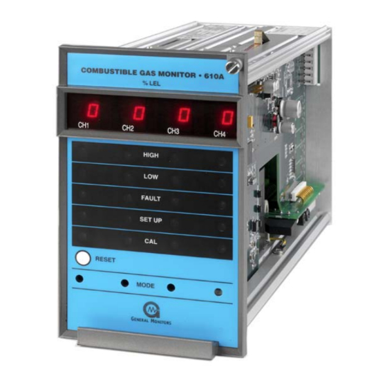
Model 610A CAUTION: The Model 610A Controller is easy to install and operate. However, one should fully read and understand this manual before attempting to place the system in service. Figure 1: Model 610A Controller Controller The Model 610A Controller is a four-channel system where the controller continuously monitors the inputs of four sensors. -
Page 11: Sensor Assembly
Set points for High and Low alarms are adjustable from 5 to 60% LEL in the FM unit. NOTE: A service-loop is necessary between the Model 610A Controller’s rear panel terminals and field/power wiring. This service loop permits the controller to be removed or slid forward for various adjustments and/or servicing. -
Page 12: Installation
Model 610A 2.0 Installation Location of the Controller The Model 610A Controller should be installed in a weather-protected, non-hazardous area. The following mounting hardware is available to facilitate installation: Part Description Part Number 98mm (4”) panel mount frame P/N 10199-1 483 mm (19”) rack frame (4 controllers) -
Page 13: Battery Backup
The battery rating (ampere-hour capacity) is dictated by the length of time power outages may last. A Model 610A Controller requires approximately 2 ampere (peak) at 24 VDC. General Monitors recommends that a Lead-Acid type battery be used. This type of battery can be expected to last for several years with minimum maintenance. -
Page 14: Figure 3: Outline Drawing & Rear Terminal Connections (Ref: 20659)
Model 610A Figure 3: Outline Drawing & Rear Terminal Connections (REF: 20659) -
Page 15: Figure 4: Rear Terminal Common Relay Configuration
Model 610A Figure 4: Rear Terminal Common Relay Configuration... -
Page 16: Figure 5: Rear Terminal Discrete Relay Configuration
Model 610A Figure 5: Rear Terminal Discrete Relay Configuration... -
Page 17: Analog Output Connection
Model 610A Analog Output Connection CAUTION: The analog output must be either used or jumpered. If not, the Model 610A indicates a fault in the normal mode with the display reading “AO” and the FAULT LED flashing. The two analog output terminals AO (+) and AO (-) are located on the rear panel. The analog output is 0 –... -
Page 18: Environmental Factors
Sensor Installation Various types (P/N’s) of sensors can be provided with the Model 610A Controller. However, the installation method is identical in all cases. Please refer to Section 7.6. The sensor assembly is used most often. It consists of P/N 10001-1 sensor plus GMI P/N 10252-1 Sensor Housing. -
Page 19: Table 2: Terminal Colors
Model 610A General Monitors recommends the use of shielded cable generally, though in some cases it is not an absolute necessity. Due to the low levels of sensor signal voltages, shielded cable is required in some installations to guard against extraneous electrical noise. -
Page 20: Figure 6: Junction Box Assembly - Sensor
Model 610A Figure 6: Junction Box Assembly – Sensor... -
Page 21: Alarm Wiring Connections
Model 610A SENSOR GUARDS PART NUMBER DESCRIPTION 1800822 DUST GUARD 10395-1 SPLASH GUARD 10110-1 DUST GUARD WITH DISPOSABLE SCREEN Table 4: Sensor Guards CAUTION: Always mount sensors pointing downward, so that water does not accumulate on the sensor head. Mounting must be as free from shock and vibration as possible, and convenient for calibration checks. -
Page 22: Special Voting Option
If the special voting option has been ordered for eight channels or more, special interconnections must be made between the Model 610A Controllers. Terminals for these interconnections are on terminal block TB2, which is the set of terminal blocks located horizontally along the bottom of the controller (Figure 11). - Page 23 Model 610A NOTE: The terminal blocks accept up to an AWG 14 wire. It is recommended that AWG 18 or AWG 20 wire be used where two leads are to be connected to the same terminal. When a voting system is in operation, all LED’s and Digital Readouts on the front of each channel function normally.
-
Page 24: Start-Up And Operation
3.0 Start-Up and Operation Types of User Interfaces User interfaces are provided so that the operator may interpret and direct the Model 610A in the performance of its various functions. User interfaces consist of a digital display, status indicators, a mode button and a reset button. -
Page 25: Initial Application Of Power
Model 610A Initial Application of Power Before applying power for the first time, double-check all wiring components. The system has a time delay feature. The High and Low alarm circuits are disabled for approximately 45 seconds after power is applied. This feature prevents false alarms while the sensor circuits are stabilizing. -
Page 26: Calibration Check Mode
Model 610A When a channel is in the Calibration, Calibration Check, Setup or Setup Check modes, a 1.5mA signal is generated by this output. During Calibration mode, the digital display shows prompts associated with the calibration procedure. During Calibration Check mode, the digital display shows the gas concentration as a flashing digit, or pair of digits. -
Page 27: Calibration Mode
NOTE: Low and High alarms are disabled during Calibration Check mode. Calibration Mode NOTE: For better results power up the sensor at least an hour before the calibration. To calibrate the Model 610A: 1. Make sure the calibration gas is the same concentration as the user specified calibration level. -
Page 28: Setup And Setup Check Modes
Model 610A 1. Wait until AC displays. Calibration cannot be aborted when (--) is flashing. 2. Press the Mode button and hold it for approximately 5 seconds. Release the button when the calibration level displays. 3. The channel returns to normal operation. -
Page 29: Entering The Password
Model 610A 2. Continuing to press and hold the Mode switch until the SETUP LED stops flashing (about five seconds more). 3. When the SETUP LED stops flashing and stays on, release the Mode button and the unit enters the Setup mode. -
Page 30: Calibration Level Option
Model 610A The Low LED on the front panel flashes while the latching/non-latching option is displayed. The display will indicate the current selection, (nL or LA). Press the Mode button to toggle the selection. Non-Latching (nL) is the factory default for this selection. -
Page 31: Setup Mode Selection Table
Model 610A. The table shown below indicates the order of options in the Setup mode. To the right of the option entry is a description of the choices that are available for that option. -
Page 32: Check Points For Calibration And Operation
3.10 Special Options 3.10.1 Optional Model 610A Controller for Zone Control (Voting) The Model 610A Controller can be supplied with a special voting option, when specified on the original order for the equipment. A system supplied for voting use, must be the... -
Page 33: Set Up Options
A maximum of four (4) Model 610A Controllers can be employed in this voting option. (Please refer to Section 7.10, for typical interconnections). NOTE: When more than one Model 610A Controller is used in a zone, all of the controllers must be mounted adjacent to one another, to keep the interconnecting leads as short as possible. -
Page 34: Maintenance
4.0 Maintenance General Maintenance Once installed, the Model 610A Controller requires little or no routine maintenance, other than periodic calibration checks. General Monitors recommends that a calibration schedule be established and adhered to. GMI also recommends that a logbook be kept, showing calibration dates and dates of sensor replacement. -
Page 35: Troubleshooting
5.0 Troubleshooting General It is highly recommended that a spare sensor be on hand at all times. General Monitors’ sensors are the most reliable, longest life, catalytic bead sensors available. Sensor failure tends to be one of the potential causes of real downtime. A full complement of other GMI recommended spare parts should also be on hand (Section 7.7). -
Page 36: Fault Codes
Model 610A Fault Codes In addition to the Fault LED on the front panel, the Model 610A provides a fault code on the digital display whenever a fault condition occurs. The Fault Codes that can appear on the digital display are:... -
Page 37: Customer Support
Email: gmme@emirates.net.ae United Arab Emirates Other Sources of Help General Monitors provides extensive documentation, white papers and product literature for its complete selection of safety products. A selection of these documents are available online at the General Monitors website at http://www.generalmonitors.com. -
Page 38: Appendix
7.0 Appendix Warranty General Monitors warrants the Model 610A Controller to be free from defects in workmanship or material under normal use and service, within two (2) years from the date of shipment. General Monitors will repair or replace, without charge, any such defective equipment found to be defective during the warranty period. - Page 39 Model 610A This sensor relies on catalytic oxidation to sense and respond to combustible gases and vapors. As the term implies, oxygen plays a very crucial part in the operation. If there is a depletion of oxygen, there will be a loss of response from the sensor. If the combustible gas is in mixture with nitrogen or some other inert gas, there may be no response at all, depending on the level of oxygen present.
-
Page 40: General Specifications - Controller
Model 610A General Specifications - Controller 7.3.1 Mechanical Specifications Dimensions: 4.0”W x 6.9”H x 11.5”D (102mm x 175mm x 292mm) Weight: 6.2 lbs. (2.86 kg) Mounting Configuration: Rack, panel, wall 7.3.2 Environmental Specifications Temperature Range: 32°F to 140°F (0°C to 60°C) Storage Temperature: -4°F to +149°F (-20°C to 65°C) -
Page 41: Cable Requirements
4800 2320 7600 Table 10: Maximum Cable Lengths Sensors The following is a list of GMI sensors available for use with the Model 610A Controller: PART NUMBER DESCRIPTION 10001-1 Standard Industrial Combustible Gas Sensor. Used for most hydrocarbons and hydrogen. Temperature range –65°F to +200°F (-55°C to +93°C). -
Page 42: Accessories
Europe. Accessories 7.7.1 Calibration Equipment Calibration accessories may be purchased from General Monitors. Contact the factory, or your local representative, for technical or ordering information. The Portable Calibration Chamber is used to calibrate sensors for any specific combustible vapor, which has a flash point below ambient temperature. The customer must provide his own sample of the liquid to use with the chamber. -
Page 43: Recommended Spare Parts
7.7.2.4 Sensor Flow Chamber (P/N 10066) The General Monitors’ Sensor Flow Chamber is constructed of aluminum (optional stainless steel construction available). The chamber has an internal thread into which a sensor may be screwed, and two threaded ports, which accept ¼ inch tube fittings. The chamber is designed for insertion into a sampling system. -
Page 44: Sample Calibration Schedule And Checklist
Model 610A Sample Calibration Schedule and Checklist To perform a Calibration Check or Calibration, refer to Sections 3.5 and 3.6. Sensor Serial Number Location ___________________ _____________________ 1. Installation and Preliminary calibration. Record Date: __________________ date after preliminary calibration is done. -
Page 45: Product Configuration Tables
Model 610A 7.10 Product Configuration Tables MODEL 610A FOUR CHANNEL COMBUSTIBLE GAS CONTROLLER A. CONTROLLER 610A Model 610A Controller 6.2 lbs. 1 (Std) P1 110 VAC/24VDC 220 VAC/24 VDC RELAY – ALARM (STD) COMMON RELAYS/COMMON ALARMS DISCRETE RELAYS/COMMON ALARMS DISCRETE RELAYS/DISCRETE ALARMS RELAY –... -
Page 46: Table 13: Product Configuration Tables
Model 610A E. VERSION (STD) VER1 FM VERSION VER2 NON-FM VERSION F. ZONE CONTROLLER ZONE CONTROLLER ON (STD) ZONE CONTROLLER OFF G. ACTIVE CHANNELS Controller Only 4.5 Lbs. One Active Channel Sensor Housing 3.0 Lbs. Sensor Simulator Combustible G 0.5 Lbs. -
Page 47: Engineering Documentation
Model 610A 7.11 Engineering Documentation 7.11.1 Panel Assembly, Panel Mount – 98, Ref: 10199C Figure 10: Panel Assembly, Panel Mount –98, Ref: 10199C... -
Page 48: Interconnection Drawing Zone Control Model 610A Controller
Model 610A 7.11.2 Interconnection Drawing Zone Control Model 610A Controller Figure 11: Interconnection Drawing Zone Control Model 610A Controller... - Page 49 ADDENDUM Product Disposal Considerations This product may contain hazardous and/or toxic substances. EU Member states shall dispose according to WEEE regulations. For further General Monitors’ product WEEE disposal information please visit: www.generalmonitors.com/customer_support/faq_general.html All other countries or states: please dispose of in accordance with existing federal, state and local...
- Page 50 Model 610A Index accessories, 37 on/off switch, 6 active bead, 33 periodic calibration check, 3 air currents, 11 periodic calibration checks, 28 alarm wiring connections, 15 portable calibration chamber, 37 analog output connection, 11 portable purge calibrator, 20 battery backup, 7...
Need help?
Do you have a question about the 610A and is the answer not in the manual?
Questions and answers