Table of Contents
Advertisement
Quick Links
Advertisement
Table of Contents

Related Manuals for Hanna Instruments Pool Line HI987134


Summary of Contents for Hanna Instruments Pool Line HI987134
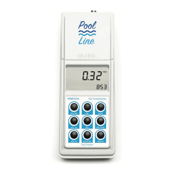
- Page 1 HI987134 ISO Portable Turbidity Meter with Fast Tracker™...
- Page 2 If you need additional technical information, do not hesitate to e‑mail us at tech@hannainst.com or view our worldwide contact list at www.hannainst.com. All rights are reserved. Reproduction in whole or in part is prohibited without the written consent of the copyright owner, Hanna Instruments Inc., Woonsocket, Rhode Island, 02895, USA.
-
Page 3: Table Of Contents
TABLE OF CONTENTS 1. PRELIMINARY EXAMINATION ....................5 2. SPECIFICATIONS ......................... 6 3. GENERAL DESCRIPTION ....................... 7 4. ABBREVIATIONS ......................... 7 5. TAG IDENTIFICATION SYSTEM ....................8 6. PRINCIPLE OF OPERATION ....................9 6.1. LOW-TURBIDITY MEASUREMENTS ................9 7. MEASUREMENT UNITS ......................9 8. - Page 4 15. TAG INSTALLATION ......................32 16. LED REPLACEMENT ......................32 17. BATTERY MANAGEMENT ....................33 17.1. BATTERY REPLACEMENT ..................33 17.2. USING AN AC ADAPTER ..................34 18. PC INTERFACE ........................ 34 19. ERROR CODES ........................ 35 20. ACCESSORIES ......................... 36 CERTIFICATION ........................
-
Page 5: Preliminary Examination
1. PRELIMINARY EXAMINATION Remove the instrument and accessories from the packaging and examine it carefully. For further assistance, please contact the local Hanna Instruments office or e-mail us at tech@hannainst.com. HI987134 is delivered in a rugged carrying case and is supplied with: •... -
Page 6: Specifications
2. SPECIFICATIONS 0.00 to 9.99 FNU Range 10.0 to 99.9 FNU 100 to 1000 FNU Range selection Automatically 0.01 FNU from 0.00 to 9.99 FNU Resolution 0.1 FNU from 10.0 to 99.9 FNU 1 FNU from 100 to 1000 FNU Accuracy ±2% of reading plus 0.1 FNU Repeatability... -
Page 7: General Description
3. GENERAL DESCRIPTION HI987134 is an ISO 7027 compliant portable turbidimeter, designed for water-quality measurements, that provides reliable and accurate readings on low-turbidity values. Depending on required accuracy, the user can select between normal, continuous or signal averaging measurement modes. It has an advanced optical system that uses a Light Emitting Diode (LED) and two detectors that allows for accurate and repeatable readings. -
Page 8: Tag Identification System
5. TAG IDENTIFICATION SYSTEM Hanna Instruments is the first manufacturer of turbidity instruments that added the unique Tag Identification System (T.I.S.) to its portable meters. T.I.S. meets the more restrictive needs of users, combining all advantages of this system with measurements and data management. -
Page 9: Principle Of Operation
6. PRINCIPLE OF OPERATION Water turbidity is an optical property that causes light to be scattered and absorbed, not transmitted. The scattered light passing through a liquid is primarily caused by suspended solids. The higher the turbidity, the greater the amount of scattered light. The light beam that passes through the sample is scattered in all directions by the particles. -
Page 10: Functional Description
8. FUNCTIONAL DESCRIPTION 8.1. INSTRUMENT LID CLOSED LID OPENED BATTERY COVER REMOVED 1. Cuvette lid Lid must be closed during measurement. 2. Cuvette holder Cuvette mark and holder mark must be aligned when inserting the cuvette into the holder. 3. Liquid Crystal Display (LCD) 4. -
Page 11: Connectors
8.2. CONNECTORS 1. AC adapter connector, used to connect an external AC adapter. 2. RS232 connector, used to transfer data through the RS232 connection using HI920011 serial cable to connect to the PC. 3. Tag reader connector, used to read the location identification number during logging by touching the tag with the connector. -
Page 12: Keypad
8.4. KEYPAD 1. CAL key, press to enter or exit calibration. When in Setup, used to start or stop editing a parameter. 2. ON/OFF key, press to turn the instrument ON/OFF. 3. GLP key, press to enter or exit GLP feature. When in Setup, used to increase the set values. -
Page 13: General Tips For Accurate Measurements
9. GENERAL TIPS FOR ACCURATE MEASUREMENTS 9.1. CUVETTE PREPARATION The cuvette is part of the optical system as the light reaches the sample by passing through the cuvette glass. Measurements are affected by dirt, dust, scratches, or fingerprints present on the cuvette surface, and so special care must be taken during sample preparation. - Page 14 Warning: Do not apply the oil in excess, it may retain dirt or contaminate the cuvette holder of the instrument and alter the turbidity readings. To correctly oil a cuvette: 1. Apply a few drops of oil. 2. Wipe the cuvette thoroughly with a lint-free cloth. 3.
- Page 15 6. Use a water-resistant pencil to mark this position on the thicker white band on top of the cuvette. Always use this position to align the cuvette with the mark on top of the instrument. Multiple Matching For correct multiple matching: 1.
-
Page 16: Sampling Technique
9.2. SAMPLING TECHNIQUE For consistent results, when selecting a representative sample: • Gently mix the water before taking the sample. • If the sample is taken from a pipe, discard the first few liters. • If measuring a non-uniform source, collect samples from different places and mix them. When measuring a collected sample: •... - Page 17 Warning: Changing the surface tension will cause a rapid settling of particles that cause turbidity. Sample should be analyzed as soon as possible. Surfactant contribution to the turbidity readings is negligible. Ultrasonic Bath Ultrasonic waves, though efficient in removing air bubbles, should be used with care as can alter sample turbidity characteristics, by modifying the shape and size of particles which cause turbidity.
-
Page 18: Measurement Procedure
10. MEASUREMENT PROCEDURE General Guidelines • Use cuvettes without scratches or cracks. • Cap the cuvettes to avoid sample spillage. • Close the lid during measurement. • Keep the lid closed when not in use to prevent dust or dirt from entering. •... - Page 19 Normal Measurement Used for stable samples when normal accuracy is required, normal measurement takes about 10 seconds. During normal measurement AVG tag is not displayed and the LED is on for a minimum of 7 seconds. 1. Press READ to start the measurement. The display will show blinking dashes and the icons for cuvette, detectors and LED will appear during measurement.
- Page 20 3. The final averaged result is displayed in FNU. Range & Units HI987134 automatically selects the correct range for highest accuracy. If the measured value is higher than 1000 FNU (over range), the maximum value is displayed blinking.
-
Page 21: Calibration
11. CALIBRATION HI987134’s calibration procedure compensates for LED aging or changing. Supplied calibration solutions or user-own standards can both be used. The instrument is supplied with 4 AMCO standards: <0.1 FNU, 15 FNU, 100 FNU and 750 FNU, specially designed for this instrument. The turbidity standards have a shelf life and should not be used passed expiration date. -
Page 22: Calibration Procedure
11.2. CALIBRATION PROCEDURE For best results follow correct measurement techniques. When calibrating using formazin standards, gently mix the cuvettes for 1 minute and allow the standard to settle for another minute before calibrating. Calibration can be performed in two-, three-, four-points. To stop calibration, press CAL or ON/OFF key. - Page 23 At the end of the measurement, the third calibration point (100 FNU) is displayed on the first LCD line, “CAL P.3” on the second LCD line with READ tag blinking. <0.1 9. Press CAL to exit calibration or continue to Three-Point Calibration procedure. The instrument memorizes the two-point calibration data and returns to measurement mode.
-
Page 24: Out Cal Range Function
At the end of the measurement, the four-point calibration is memorized and the instrument automatically returns to measurement mode. 11.3. OUT CAL RANGE FUNCTION Recommended calibration range for correct measurements is up to 40 FNU for two-point calibration and up to 150% of the third point value for three-point calibration. LCD displays a blinking CAL tag each time measurements are taken outside the calibration range. -
Page 25: Logging
12. LOGGING Each measurement’s information (date, time and tag ID) is stored for further analysis. 12.1. LOGGING A MEASUREMENT The log function is available after a valid measurement. 1. Press LOG/CFM when the measured value is displayed. The instrument asks for READ TAG to identify the sampling location. The location for the new record is also displayed on second LCD line. - Page 26 • When scrolling the log, the number of the record is displayed for one second on second LCD line, together with TAG if sampling location has been identified. • An accoustic signal (error beep) indicates all logged records have been scrolled through. Viewing a Record Press READ...
-
Page 27: Logging Warnings
Deleting All Records 1. Press SETUP/DEL while in delete all records panel. 2. Press LOG/CFM to confirm or READ to cancel. Last record is deleted. The instrument returns to the previous record’s first panel. After deletion dashes are displayed briefly and the instrument returns to idle mode. 12.3. -
Page 28: Good Laboratory Practice (Glp)
13. GOOD LABORATORY PRACTICE (GLP) GLP feature displays last calibration data, or allows calibration data to be deleted. 1. Press GLP to enter or exit GLP data panel. 2. Press READ to scroll through the GLP data: • The date of the last calibration, in YYYY.MM.DD format. If no calibration was performed, the factory calibration message “F.CAL”... -
Page 29: Setup
14. SETUP Setup mode allows viewing and modifying the instrument parameters. Note: Blinking CAL tag during setup mode indicates to press CAL for parameters editing. 1. Press SETUP/DEL key to enter or exit Setup mode. 2. Press GLP / AVG keys to select the desired panel with parameter to be edited. Beep Options: ON or OFF This parameter indicates error conditions, a wrong key press or a tag read. - Page 30 3. Press GLP / AVG keys to set the values. 4. Press LOG/CFM to save. Alternatively, press CAL to exit without saving the changes. Time Options: hour, minute 1. Press CAL in set time panel. The time format is hh:mm. Hour and CFM tag are displayed blinking. 2.
- Page 31 Baud Rate Options: 1200, 2400, 4800 and 9600 HI987134 has RS232 and USB link. When one connection is used, the other becomes inactive. To successfully communicate with the PC, the same baud rate must be selected on the instrument and in the PC application.
-
Page 32: Tag Installation
15. TAG INSTALLATION The tag is housed in a rugged metal that can withstand harsh environments. However, it is better to protect the tag from direct rain. 1. Place the tag near a sampling point. 2. Fix it securely with the provided screws. 3. -
Page 33: Battery Management
17. BATTERY MANAGEMENT At power on, remaining battery percentage is displayed. • Battery level is measured each time the LED is turned on. If the battery level is less than 10%, the battery tag is displayed blinking and batteries need to be replaced. •... -
Page 34: Using An Ac Adapter
17.2. USING AN AC ADAPTER When used in laboratory, HI987134 can be powered from the AC adapter. (see ACCESSORIES section to select the correct AC adapter). 1. Connect the AC adapter to the instrument (see CONNECTORS section). 2. It is not necessary to turn the instrument off when connecting the external adapter. Note: The connection to the external adapter will not recharge the batteries. -
Page 35: Error Codes
SOLUTION Err1; Err2; Err3 Critical errors Call Hanna Instruments service Err6; Err7; Err8 Instrument beeps and shuts down. Call Hanna Instruments service Instrument beeps shortly twice and Reset EEPROM by pressing Err4 shuts down after 10 seconds simultaneously GLP+AVG keys. -
Page 36: Accessories
20. ACCESSORIES HI710005 Voltage adapter from 115V to 12 Vdc (USA plug) HI710006 Voltage adapter from 230V to 12 Vdc (European plug) HI710012 Voltage adapter from 230V to 12 Vdc (UK plug) HI710014 Voltage adapter from 230V to 12 Vdc (Australia plug) HI731318 Cloth for wiping cuvettes (4 pcs.) HI731331... -
Page 37: Certification
CERTIFICATION All Hanna Instruments conform to the CE European Directives. Disposal of Electrical & Electronic Equipment. The product should not be treated as household waste. Instead hand it over to the appropriate collection point for the recycling of electrical and electronic equipment which will conserve natural resources. -
Page 38: Warranty
Damage due to accidents, misuse, tampering or lack of prescribed maintenance is not covered. If service is required, contact your local Hanna Instruments Office. If under warranty, report the model number, date of purchase, serial number and the nature of the problem. If the repair is not covered by the warranty, you will be notified of the charges incurred. - Page 39 Hanna Instruments reserves the right to modify the design, construction or appearance of its products without advance notice.
- Page 40 World Headquarters Hanna Instruments Inc. Highland Industrial Park 584 Park East Drive Woonsocket, RI 02895 USA www.hannainst.com MAN987134 Printed in ROMANIA...
Need help?
Do you have a question about the Pool Line HI987134 and is the answer not in the manual?
Questions and answers