
Related Manuals for Hanna Instruments HI98594


Summary of Contents for Hanna Instruments HI98594
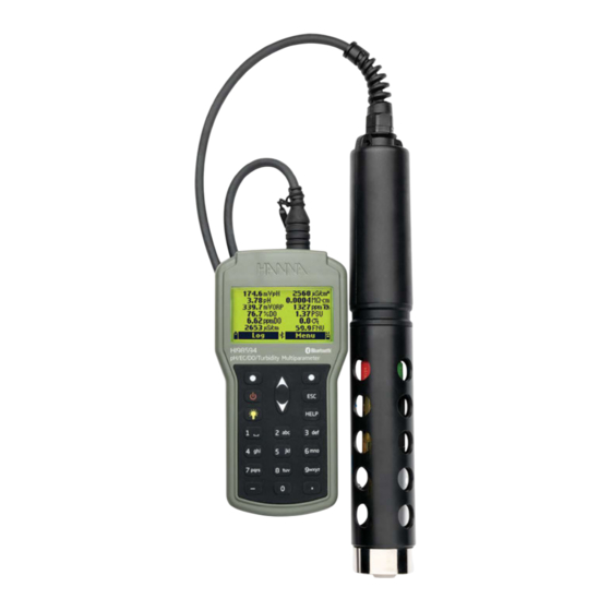
- Page 1 INSTRUCTION MANUAL HI98594 Portable ® pH / EC / Turbidity / opdo Meter ® with Bluetooth Technology Hanna Instruments Inc., 584 Park East Drive, Woonsocket, RI 02895 USA www.hannainst.com...
- Page 2 All rights are reserved. Reproduction in whole or in part is prohibited without the copyright owner’s written consent, Hanna Instruments Inc., Woonsocket, Rhode Island, 02895, USA. Hanna Instruments reserves the right to modify the design, construction, or appearance of its products without advance notice.
- Page 3 TABLE OF CONTENTS 1. Preliminary Examination ......4 9. Maintenance ..........47 9.1. General Maintenance ........ 47 2. Battery Safety ..........5 9.2. Sensor Maintenance ......... 48 3. General Description & Intended Use ... 6 9.3. Sensor Replacement ........ 48 4.
- Page 4 Preliminary Examination 1. PRELIMINARY EXAMINATION Remove the instrument and accessories from the packaging and examine it carefully. ® For further assistance, please contact your local Hanna Instruments office or email us at tech@hannainst.com. Each HI98594 is delivered in a rugged carrying case and is supplied with: •...
- Page 5 Battery Safety 2. BATTERY SAFETY The coin‑cell battery is replaceable by a professional service center only. WARNING • INGESTION HAZARD: This product contains a button cell or coin battery. • DEATH or serious injury can occur if digested. • A swallowed button cell or coin battery can cause Internal Chemical Burns in as little as 2 hours. •...
- Page 6 General Description & Intended Use 3. GENERAL DESCRIPTION & INTENDED USE HI98594 is a portable logging multiparameter system (meter and probe) that monitors up to 14 different water quality parameters (7 measured and 7 calculated) such as pH, ORP, conductivity, turbidity, pressure, dissolved oxygen and temperature.
- Page 7 Specifications 4. SPECIFICATIONS 4.1. SYSTEM SPECIFICATIONS pH / mV 0.00 to 13.00 pH Range ±600.0 mV 0.01 pH Resolution 0.1 mV ±0.05 pH Accuracy* ±3.0 mV • One point using HI9828‑20 Quick calibration solution Calibration • Up to three points using pH 4.01, pH 6.86, pH 7.01, pH 9.18, pH 10.01 standard buffers and one custom buffer Range ±2000.0 mV...
- Page 8 8 Specifications Conductivity 0 to 200 mS/cm Range 0 to 400 mS/cm (absolute) • Manual 1 µS/cm 0.001 mS/cm; 0.01 mS/cm; 0.1 mS/cm; 1 mS/cm • Automatic 1 µS/cm from 0 to 9999 µS/cm 0.01 mS/cm from 10.00 to 99.99 mS/cm Resolution 0.1 mS/cm from 100.0 to 400.0 mS/cm •...
- Page 9 Specifications Salinity Range 0.00 to 70.00 PSU Resolution 0.01 PSU Accuracy ±2% of reading or ±0.01 PSU, whichever is greater Calibration One point, using a custom solution Seawater Sigma Range 0.0 to 50.0 σ , σ , σ Resolution 0.1 σ , σ...
- Page 10 10 Specifications Temperature −5.00 to 50.00 °C Range 23.00 to 122.00 °F 268.15 to 323.15 K 0.01 °C Resolution 0.01 °F 0.01 K ±0.15 °C Accuracy ±0.27 °F ±0.15 K Calibration Automatic at one custom point Other Specifications −5 to 50°C Temperature compensation Automatic 23 to 122 °F...
- Page 11 Specifications 4.2. PROBE SPECIFICATIONS pH or pH / ORP Sensor inputs EC / Turbidity Dissolved Oxygen Sample environment Fresh, brackish, seawater Protection rating IP68 −5.0 to 50.0 °C Operating temperature 23.0 to 122.0 °F −20.0 to 70.0 °C Storage temperature −4.0 to 158.0 °F Immersion depth 20 m (66’)
- Page 12 12 Specifications Measurement unit mV (pH) mV (ORP) 0.00 to 12.00 pH Measure range ±600.0 mV (pH) ±2000.0 mV (ORP) Color code −5.0 to 50.0 °C Operational temperature 23.0 to 122.0 °F HI7698194‑1 pH/ORP Glass (pH) and ORP (platinum) Junction Wick Materials Body...
- Page 13 Specifications % saturation Measurement unit mg/L 0.0 to 500.0 % saturation Measure range 0.00 to 50.00 mg/L Color code Green HI7698594‑5 −5.0 to 50.0 °C Operational temperature Dissolved Oxygen 23.0 to 122.0 °F Sensor type Optical Immersion depth 20 m (66’) Length 99 mm (3.9”) Dimensions...
- Page 14 Functional & Keypad Description 5. FUNCTIONAL & KEYPAD DESCRIPTION Front View H H I I 9 9 8 8 5 5 9 9 4 4 pH/EC/DO/Turbidity Multiparameter Top View HELP 13 14 15 wxyz pqrs 1. Liquid Crystal Display (LCD) 12.
- Page 15 Functional & Keypad Description HI7698594 Multisensor Probe 1. Strain relief 2. Sensor body 3. Long protective shield › HI7698296 4. Short protective shield › HI7698295 Cover option when EC / Turbidity sensor is not used. Ordered separately.
- Page 16 6. GENERAL OPERATIONS 6.1. BATTERY CAPACITY, REPLACEMENT, RECHARGING HI98594 is equipped with a primary, internal Li‑ion battery and supplied with 4 alkaline, 1.5 V AA batteries. When the primary, rechargeable battery is completely discharged (0%), the meter will switch to the backup, alkaline batteries.
- Page 17 General Operations Recharging the Li-ion battery Plug the USB cable (supplied) into the USB‑C port on top of the instrument and into a USB‑C power adapter or a laptop / PC port. Battery charging animated icon is displayed during recharge (bottom right corner of the screen), the battery level (as a percentage of fully charged), and the battery charging status (On or Off) are also displayed.
- Page 18 General Operations 6.2.1. Probe and Sensor Preparation Remove the protective shield from the probe and set aside. DO Smart Cap hydration Hydrate the HI764113‑1 Smart Cap following the instructions below. a. Remove the optical cap from the cap kit. b. Place the cap in a container with purified water. There should be just enough liquid for the cap end to be submerged in the water.
- Page 19 • Press the On / Off key to turn the meter on. ® At start‑up the display will show the Hanna Instruments logo, meter name, and firmware version. After the initialization has been completed, if the probe is connected, the meter displays the Probe Status or the Tutorial Mode message.
- Page 20 General Operations 6.5. BASIC OPERATIONS The main operating modes are setup, measurement, and logging. The instrument can be configured to display measurement data for all enabled parameters. • Press the arrow keys to scroll between measured data in all available parameters. The display has a feature that automatically sizes the digits to fit the screen.
- Page 21 General Operations 6.7. FUNCTIONAL DIAGRAM OF THE INSTRUMENT Menu and Log functional keys help user navigate through all measurement operations. The following diagrams present an overview of possible functions. Menu Parameter Selection Parameter Units One sample on meter Parameter Setup Parameter Coefficients Start Meter Log Averaging...
- Page 22 Parameter Setup 7. PARAMETER SETUP • Press Menu from the measurement screen. • Use the arrow keys to highlight “Parameter Setup” then press Select. • Use the arrow keys to highlight the desired option then press Select. Note: Data saved on the meter will be changed to selected parameter units or coefficients.
- Page 23 Parameter Setup 7.1. PARAMETER SELECTION • Use the arrow keys to scroll through the list of available parameters. • Press the corresponding functional key to enable or disable selected parameter. A checked box indicates that the parameter is enabled. Note: When the password protection is enabled, authentication will be required before any parameter modification.
- Page 24 Parameter Setup Press Select to confirm or the ESC key to return to the previous screen. Resistivity Unit Option: Ω·cm, kΩ·cm, MΩ·cm Resistivity is calculated from the conductivity measurement. Press the functional key to select the desired resistivity unit. Seawater Sigma (σ) Unit Option: σ...
- Page 25 Parameter Setup Absolute EC Resolution Option: Auto, Auto mS/cm, 1 μS/cm, 0.001 mS/cm, 0.01 mS/cm, 0.1 mS/cm, 1 mS/cm • Press Modify and use the arrow keys to select the desired absolute EC resolution. • Press Select to confirm or the ESC key to return to the previous screen. Auto The meter automatically chooses the range (µS/cm or mS/cm) to optimize the measurement.
- Page 26 Parameter Setup 7.3. PARAMETER COEFFICIENTS EC Reference Temperature Option: 20 °C or 25 °C This value is used for temperature compensated conductivity. All EC measurements will be referenced to the conductivity of a sample at this temperature. Press the functional key to select the desired EC reference temperature. EC Temperature Coefficient (Beta, ß) Option: 0.00 to 6.00 %/°C ß...
- Page 27 Parameter Setup 7.4. AVERAGING Option: 1 to 20 samples Averaging is a software filter to minimize measurement noise and provide more stable readings. It is particularly useful to get a representative reading of the “average” value from flowing water. Averaging will affect all measurements. Note: If a fast response is needed, this value should be kept low.
- Page 28 Calibration 8. CALIBRATION • Press Menu from measurement screen. • Use the arrow keys to highlight Calibration then press Select. • Use the arrow keys to highlight the desired option then press Select. All calibration data is stored in the non volatile probe memory, allowing probes to be connected to different meters without recalibration.
- Page 29 Calibration 8.1. QUICK CALIBRATION The quick calibration provides a single point calibration for pH, EC, and DO. Users can select to calibrate all sensors or any sensor combination. Press Skip to escape a sensor calibration and move to next in series. Note: If the tutorial mode is enabled, press Tutorial and follow the messages on the screen.
- Page 30 Calibration 10. The message “Empty the beaker. Shake the probe and put it in the beaker again” will appear. Unscrew the calibration beaker and discard the solution. 11. Shake any remaining solution off the probe. No droplets should remain on the DO sensor cap sensing surface. Note: Do not wipe the sensing surface as damage may occur.
- Page 31 Calibration 8.2. pH CALIBRATION Calibration Options Calibrate pH The user can perform a new calibration using up to 3 buffers. Option to select from pH 4.01, 6.86, 7.01, 9.18, 10.01; or use a custom buffer. For a three‑point calibration, new data overwrites existing calibration points. With a single or two‑point calibration the meter will also use information from the previous calibration, if available.
- Page 32 Calibration 12. Press Accept to confirm the buffer value. 13. Once the reading has stabilized the countdown timer will count down until the display shows the “Ready” message. Press Confirm to accept the calibration point. 14. After the calibration point is confirmed, to avoid cross‑contamination, empty and rinse the calibration beaker. 15.
- Page 33 Calibration Error Messages “Check sensor” is displayed when: • the electrode is broken, very dirty, or the user has attempted to calibrate the same buffer value twice. • an erroneous slope condition has been detected i.e. the slope difference between the current and previous calibration exceeds the slope window (80% to 110%).
- Page 34 Calibration 8.3. ORP CALIBRATION ORP calibration is used to compensate for changes in the potential due to contamination of the sensing surface and drift in the reference electrode. Calibration is not typically required but it does establish a baseline that can be used for future validations. Note: ORP values are not temperature compensated and can change with temperature.
- Page 35 Calibration 11. The stability counter will count down until the display shows the “Ready” message. 12. Press Confirm to accept the calibration point. The message “Storing” followed by “Calibration completed” will be displayed. 13. Press Ok to return to the calibration menu or Measure to return to the measurement screen. Error Message “Wrong standard”...
- Page 36 Calibration Note: If the tutorial mode is enabled, press Tutorial and follow the messages on the screen. % DO Saturation Calibration • Remove the shield from the probe and rinse the probe with purified water. • Shake any remaining solution off the probe. No droplets should remain on the DO sensor sensing surface.
- Page 37 Calibration Single point Calibration at 100 %, 0 %, or Custom value 1. Calibrate at 100.0% • Select Cal.point then select 100.0%. • Follow steps 1–5 from Calibration at 100% Saturation section. • Press Confirm when “Ready” message appears. 2. Calibrate at 0.0% •...
- Page 38 Calibration 6. Only engage the calibration beaker one or two threads onto the probe body! Some solution may overflow! 7. Wait a few minutes for the measurement to stabilize. 8. Use the arrow keys to select DO Concentration from DO Calibration list. 9.
- Page 39 Calibration 8.5. CONDUCTIVITY CALIBRATION Conductivity calibrations are used to correct for variations in cell factors. Oily coatings and biological contaminations can cause changes in the cell geometry. The EC electrodes are located inside two small channels on the bottom of the sensor. They can be cleaned with the small brush from the maintenance kit.
- Page 40 Calibration 7. Use the arrow keys to select Conductivity from the Conductivity Calibration list. 8. Press Start to start the calibration. 9. If necessary, press Cal. point to select the correct standard. 10. To enter a user‑defined standard, press Custom. A text box window will appear.
- Page 41 Calibration 6. Screw the calibration beaker completely onto the probe body. Some solution may overflow! 7. Wait a few minutes for the measurement to stabilize. Use the arrow keys to select Absolute Conductivity from the Conductivity Calibration list. 8. Press Start to start the calibration. A text box window will appear.
- Page 42 Calibration 9. Press Accept to confirm the standard value. 10. The stability counter will count down until the display shows the “Ready” message. 11. Press Confirm to save the calibration. The message “Storing” followed by “Calibration completed” will be displayed. 12.
- Page 43 The STDVB polymer standards are available in ready‑to‑use concentrations to ensure accurate turbidity calibrations and measurements. 16. Accessories for information regarding Hanna Instruments calibration solutions. Note: Turbidity standard formulations made with polystyrene beads are instrument-specific and cannot be substituted with standards made for another turbidity sensor.
- Page 44 Calibration 10. Once the reading has stabilized, the display shows the “Ready“ message. 11. Press Confirm to accept the calibration point. 12. After the calibration point is confirmed, to avoid cross‑contamination, immerse the sensors in the next calibration standard rinse solution and stir gently. 13.
- Page 45 Calibration 8.7. TEMPERATURE CALIBRATION Calibration Options Calibrate Temperature The user can perform a single point calibration. Note: Temperature calibration should be made prior to sensor calibration. Restore Factory Calib. Clears previous user calibration. Procedure Note: If the tutorial mode is enabled, press Tutorial and follow the messages on the screen. 1.
- Page 46 Calibration 8.8. PRESSURE CALIBRATION Calibration Options Custom Pressure The user can perform a single point calibration. Note: Pressure calibration should be made prior to DO sensor calibration. Restore Factory Calib. Clears previous user calibration. Procedure Note: If the tutorial mode is enabled, press Tutorial and follow the messages on the screen. 1.
- Page 47 Maintenance 9. MAINTENANCE 9.1. GENERAL MAINTENANCE • Inspect all sensor connectors for corrosion. Replace sensors if necessary. • Inspect sensor o‑ring for nicks or other damage. Replace the o‑ring if necessary. Use only the supplied grease as some lubricants can cause the o‑ring to expand. •...
- Page 48 Maintenance 9.2. SENSOR MAINTENANCE For correct sensor maintenance: 1. Unscrew to remove the protective shield from the probe body and set aside. 2. Use the calibration beaker for cleaning 3. Use HI76984942 probe maintenance kit. See section 16. Accessories for details. Note: If the sensors are removed from the probe body, the body of the sensors must be dried prior to installation to prevent water from entering the sockets.
- Page 49 Maintenance 9.4. SENSOR TYPES & DESCRIPTIONS HI7698194‑0 combination pH sensor It features a PEI‑body pH sensor with a glass bulb and a silver/silver chloride double junction reference with gelled electrolyte. HI7698194‑1 combination pH / ORP sensor It features a PEI‑body pH sensor with a glass bulb, a platinum sensor for redox measurements and a silver/ silver chloride double junction reference with gelled KCl electrolyte.
- Page 50 Maintenance 9.5. SENSOR INSTALLATION 9.5.1. General Guidelines To make installation easier, the probe has three sensor‑connector sockets identified with color‑coded triangles. connector 1 › HI7698194‑1 pH / ORP sensor or HI7698194‑0 pH sensor connector 2 › HI7698594‑5 Optical Dissolved Oxygen sensor ...
- Page 51 Maintenance 6. Remove the syringe plunger. 7. Cut the top off supplied sachet with silicone grease and empty contents into the syringe. Using the syringe, sparingly lubricate the o‑ring with a thin film of the supplied grease. Avoid getting grease or fingerprints onto the optical window. Do not substitute other grease or lubricants as it may cause the o‑ring to swell.
- Page 52 System Setup 10. SYSTEM SETUP • Press Menu from measurement screen. • Use the arrow keys to highlight System Setup then press Select. • Use the arrow keys to highlight the desired option then press Select. Note: When the password protection is enabled, authentication will be required before any modification. 10.1.
- Page 53 System Setup Time Option: 12 or 24 hours • Press Modify and set the time using the keypad. • Press Format to change between 12 and 24 hours. When the 12 hour format is used, use the down arrow to get to the ante or post meridian abbreviation. The first letter can be changed by pressing any key.
- Page 54 System Setup • Press Wake up to reactivate the display. Tutorial Option: Enabled or Disabled When enabled, the user will be guided step‑by‑step through the sensor preparation, sensor maintenance, sensor installation and calibration procedures. Key Beep Option: Enabled or Disabled When enabled, an acoustic signal is heard every time a key is pressed.
- Page 55 System Setup • Press Accept to save or press ESC key to return to the menu. LCD Backlight Option: 0 to 10 This function allows the adjustment of the LCD backlight intensity. • Press Modify and use the arrow keys to change the backlight intensity. •...
- Page 56 System Setup Meter ID Option: Up to 14 characters • Press Modify to enter meter’s ID setup screen. • Use the keypad to set or change the meter’s ID. • Press Accept to save or press ESC key to return to the menu. Language �...
- Page 57 System Setup Restore Factory Settings This function restores measurement settings to their original factory values. This includes measurement units, coefficients, other measurement configurations, and all logged data. The calibration for the sensor is not affected. • Highlight Restore factory settings then press Select. •...
- Page 58 ® Bluetooth ® 11. BLUETOOTH HI98594 can be connected to the Hanna Lab App (version 3.0 or higher) using Bluetooth technology. ® The Hanna Lab App is available on the App Store and on Google Play*; and features Hanna Cloud compatibility.
- Page 59 ® Bluetooth 5.0 11.3. DELETE PAIRED DEVICES • Press Select option in Meter Setup to delete all paired devices. After selecting this option, a prompt on display is asking for confirmation. • Press Yes to confirm or No to return to the menu. “Previously paired devices removed”...
- Page 60 Status 12. STATUS • Press Menu from measurement screen. • Use the arrow keys to highlight “Status” then press Select. • Use the arrow keys to highlight the desired option then press Select. 12.1. METER STATUS Meter Status displays information related to the batteries, charging status, logging, internal temperature, password, Meter ID, serial number and firmware version.
- Page 61 Status 12.3. GLP GLP (Good Laboratory Practice) is a set of functions that allows the user to store or recall data regarding the probe calibration. GLP data stores the last five calibrations. Note: If no user calibration data is available for the selected parameter, “Factory Calibration” message is displayed. To navigate the GLP screens: •...
- Page 62 Status Conductivity Conductivity GLP screen displays: calibration point, cell constant value, offset, calibration type (conductivity, absolute conductivity or salinity), time, and date. Note: A “C” label next to the calibration point indicates a custom point, while an “H” indicates a Hanna ®...
- Page 63 Measurement 13. MEASUREMENT During measurement mode HI98594 will simultaneously measure data for all enabled parameters. Use the numbers 1 through 7 on the keypad to select the number of parameters that are shown on the screen at one time. The display will automatically resize the font.
- Page 64 Logging 14. LOGGING HI98594 and the HI7698594 multisensor probe offer two types of logging: meter only parameters, and meter and probe parameters. Meter only parameters Meter & probe parameters • From measurement mode, press Log to access Log menu. • The data logged on the meter are organized by lots.
- Page 65 Logging 5. Press OK to log the sample in the selected lot. 6. The Remarks window will open. Press Yes to add a remark to the data point or No to skip. 7. The meter will return to the measurement screen automatically. 14.2.
- Page 66 Logging 14.3. LOG RECALL Select “Log Recall” to view logs that are stored on the meter. 14.3.1. Lots Select this option to view all continuous log files saved on the meter. 1. Use the arrow keys to select the desired lot and then press View. The meter displays a summary of all data related to the selected lot: number of samples, used memory space, time and date of the first and last readings.
- Page 67 Logging Export selected log data to USB‑C Flash Drive: 1. Insert a USB‑C flash drive (or USB‑A with cable adapter) into the USB‑C connector located on the top of the meter. See section 14.5. PC Connection for details. 2. Select Export Log. “Connecting”...
- Page 68 Logging 6. Press Plot. The meter creates a list with all available parameters that can be plotted. 7. Use the arrow keys to select the parameter to be plotted. 8. Press Select to view the graph. 9. Use the arrow keys to move the cursor in the graph and highlight a sample. The sample data is displayed below the graph.
- Page 69 Logging 14.4. LOG NOTES 14.4.1. Remarks The meter can store up to 20 remarks. A remark can be associated with each sample. To add a remark: 1. Select Log Notes from the Log menu then select Remarks. The display shows a list of stored remarks. 2.
- Page 70 ‘’User data corrupted!’’ is displayed when powering up and the user data stored on meter are corrupted. Restart the meter. If the problem persists, contact your local Hanna Instruments office. “Incompatible Probe! Remove Probe!” is displayed when the connected probe is not compatible with the meter.
- Page 71 Warnings displayed at power‑on are identified using a numeric code. Some features can be accessed but with no guarantee. • Restart the meter. ® • If the problem persists, contact your local Hanna Instruments office. ‘’Error x’’ Critical errors are identified using a numeric code •...
- Page 72 Probe with 40 m (131.2’) cable Note: Probes with different cable lengths are available upon request. Meters with Probes & Sensors Ordering Information Product Details HI98594 meter HI98594 pH / ORP, EC/Turbidity, optical DO sensors probe with 4 m (13.1’) cable...
- Page 73 Accessories Quick Calibration Solutions Ordering Information Product Description HI9828-20 Quick calibration solution, 230 mL HI9828-25 Quick calibration solution, 500 mL HI9828-27 Quick calibration solution, 1 gallon (3.78 Liters) pH Buffers Ordering Information Product Description HI5004 pH 4.01 buffer solution, 500 mL HI5068 pH 6.86 buffer solution, 500 mL HI5007...
- Page 74 74 Accessories Turbidity Solutions Ordering Information Product Description HI9829-16 0 FNU calibration solution, 230 mL HI9829-17 20 FNU calibration solution, 230 mL HI9829-18 200 FNU calibration solution, 230 mL Other Ordering Information Product Description HI7698290 Short calibration beaker HI7698293 Long calibration beaker HI7698295 Short protective shield HI7698296...
- Page 75 If the instrument is to be returned to Hanna Instruments, first obtain a Returned Goods Authorization (RGA) number from the Technical Service department and then send it with shipping costs prepaid. When shipping any instrument, make sure it is properly packed for...
- Page 76 76 Regulatory Notices REGULATORY NOTICES ® Stand-alone, Bluetooth , low-energy modules All modules have identical operation. All references to US FCC Rules and Canadian RSS standards on device classification and operation, listed here under BMD‑300 Module, apply to all models noted here. Remove the battery cover to check the installed module.
Need help?
Do you have a question about the HI98594 and is the answer not in the manual?
Questions and answers