Table of Contents
Advertisement
Advertisement
Table of Contents

Subscribe to Our Youtube Channel
Related Manuals for Hanna Instruments HI98494


Summary of Contents for Hanna Instruments HI98494
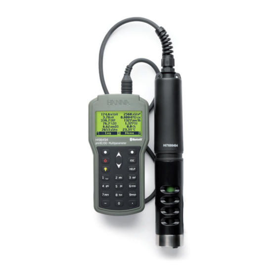
- Page 1 HI98494 Multiparameter ® Bluetooth ® Portable pH / EC / opdo Meter...
- Page 2 If you need additional technical information, do not hesitate to e‑mail us at tech@hannainst.com or view our contact list at www.hannainst.com. All rights are reserved. Reproduction in whole or in part is prohibited without the written consent of the copyright owner, Hanna Instruments Inc., Woonsocket, Rhode Island, 02895, USA.
-
Page 3: Table Of Contents
TABLE OF CONTENTS 1. PRELIMINARY EXAMINATION ....................5 2. GENERAL DESCRIPTION & INTENDED USE ................6 3. SPECIFICATIONS ......................... 7 3.1. METER SPECIFICATIONS .................... 7 3.2. PROBE SPECIFICATIONS ..................10 3.3. SENSOR SPECIFICATIONS ..................10 4. FUNCTIONAL & KEYPAD DESCRIPTION ................12 5. - Page 4 9. SYSTEM SETUP ......................... 45 9.1. METER SETUP ......................45 9.2. PROBE SETUP ......................50 ® 10. BLUETOOTH ........................ 51 11. STATUS ......................... 52 11.1. METER STATUS ..................... 52 11.2. PROBE STATUS ..................... 52 11.3. GLP ........................53 12. MEASUREMENT ......................55 13.
-
Page 5: Preliminary Examination
1. PRELIMINARY EXAMINATION Remove the instrument and accessories from the packaging and examine it carefully. For further assistance, please contact your local Hanna Instruments Office or email us at tech@hannainst.com. Each HI98494 is delivered in a rugged carrying case and is supplied with: •... -
Page 6: General Description & Intended Use
2. GENERAL DESCRIPTION & INTENDED USE HI98494 is a portable logging multiparameter system (meter and probe) that monitors up to 13 different water quality parameters (6 measured and 7 calculated) such as pH, ORP, conductivity, dissolved oxygen and temperature. The... -
Page 7: Specifications
3. SPECIFICATIONS 3.1. METER SPECIFICATIONS 0.00 to 14.00 pH* Range ± 600.0 mV 0.01 pH Resolution 0.1 mV pH / mV ± 0.02 pH Accuracy ± 0.5 mV One point, using HI9828-25 Quick calibration solution Calibration Up to three points using five standard buffers (pH 4.01, 6.86, 7.01, 9.18, 10.01) and one custom buffer Range ±... - Page 8 0 to 200 mS/cm Range 0 to 400 mS/cm (absolute) Manual 1 µS/cm; 0.001 mS/cm; 0.01 mS/cm; 0.1 mS/cm; 1 mS/cm Automatic 1 µS/cm from 0 to 9999 µS/cm 0.01 mS/cm from 10.00 to 99.99 mS/cm Resolution 0.1 mS/cm from 100.0 to 400.0 mS/cm Conductivity Automatic (mS/cm) 0.001 mS/cm from 0.000 to 9.999 mS/cm 0.01 mS/cm from 10.00 to 99.99 mS/cm...
- Page 9 0.0 to 50.0 σ , σ , σ Range 0.1 σ , σ , σ Resolution Seawater Sigma ±1.0 σ , σ , σ Accuracy Calibration Based on conductivity or salinity calibration 450.0 to 850.0 mmHg 17.72 to 33.46 inHg 600.0 to 1133.2 mbar Range 8.702 to 16.436 psi...
-
Page 10: Probe Specifications
3.2. PROBE SPECIFICATIONS Sensor Inputs Sample Environment Fresh, Brackish, Seawater Protection Rating IP68 Operating Temperature -5 to 50 °C (23.0 to 122.0 °F) Storage Temperature -20 to 70 °C (-4.0 to 158.0 °F) Maximum Depth 20 m (66’) Length 342 mm (13.5”) Dimensions (without cable) Diameter 46 mm (1.8”) Weight (with sensors) - Page 11 Measurement Unit pH, mV (pH), mV (ORP) 0.00 to 13.00 pH Measure Range ± 600.0 mV (pH) ± 2000.0 mV (ORP) Color Code Temperature Range -5 to 55 °C (23.0 to 131.0 °F) pH glass and platinum ORP HI7698194-1 Junction Wick pH/ORP Materials...
-
Page 12: Functional & Keypad Description
4. FUNCTIONAL & KEYPAD DESCRIPTION Front View 1. Liquid Crystal Display (LCD) 2. Alkaline battery level indicator 3. Functional keys, press to perform the function displayed above them on the screen 4. Power (On / Off) key, press to turn the meter on and off 5. - Page 13 Top View 12. DIN connector for probe connection 13. USB-C connector with protective cap HI7698494 multisensor probe 1. Strain relief 2. Sensor body 3. Protective shield...
-
Page 14: Sensor Preparation & Installation
5. SENSOR PREPARATION & INSTALLATION 5.1. SENSOR TYPES & DESCRIPTIONS HI7698194-0 combination pH sensor features a plastic body pH sensor with a glass bulb and a silver/silver chloride double junction reference with gelled electrolyte. HI7698194-1 combination pH / ORP sensor features a plastic body pH sensor with a glass bulb, a platinum sensor for redox measurements and a silver/silver chloride double junction reference with gelled KCl electrolyte. -
Page 15: Sensor Preparation & Conditioning
DETAIL 1 Alignment key 4 Smart Cap™ 2 O-Ring Seal 5 RFID Tag 3 Optical window 6 Embedded O sensitive luminophore with black protective layer 5.2. SENSOR PREPARATION & CONDITIONING pH/ORP Combination Sensor or pH Sensor To prepare for installation: 1. -
Page 16: Sensor Installation
To replace the Smart Cap: 1. Remove the expired Smart Cap from the sensor by squeezing the cap at the cutout arrow and pulling it off the sensor body (do not twist). 2. Remove the used o-ring by rolling it off the sensor. 3. - Page 17 3. Insert the sensor into the correctly color-coded opening while positioning the connector key toward the center of the probe. Make sure the connector is seated correctly (the sensor will no longer move freely) before tightening the locking threads with your fingers. 4.
-
Page 18: Sensor Maintenance
5.4. SENSOR MAINTENANCE For correct sensor maintenance: 1. Unscrew to remove the protective shiled from the probe body and set aside. 2. Use the calibration beaker for cleaning 3. Use HI76984942 probe maintenance kit. See section 16. ACCESSORIES for details. Note: If the sensors are removed from the probe body, the body of the sensors must be dried prior to installation to prevent water from entering the sockets. - Page 19 DO Sensor Cleaning the Smart Cap: • Use a mild detergent and a soft-bristled toothbrush (not the brush in the maintenance kit) to clean. • Rinse with water after cleaning and dry with a laboratory tissue. • Hydrate in purified water before use. Smart Caps require replacement on a yearly basis.
-
Page 20: General Operations
6. GENERAL OPERATIONS 6.1. BATTERY CAPACITY & REPLACEMENT HI98494 is equipped with a primary, internal Li-ion battery and supplied with 4 Alkaline, 1.5 V AA batteries. When the primary, rechargeable battery is completely discharged (0%), the meter will switch to the backup, Alkaline batteries. -
Page 21: Connecting The Probe
After connecting the sensors to the probe and connecting the probe to the meter, turn the meter on by pressing the On / Off key. At start-up the display will show the Hanna Instruments logo, meter name and firmware version. After the initialization has been completed, if the probe is connected, the meter displays the Probe... -
Page 22: Tutorial
The probe status screen identifies the probe and attached sensors. See section 6.4. TUTORIAL for information on the Tutorial mode. Press Measure to view the measurement screen. Press Param. to open the Parameters menu. This screen can also be accessed from the main menu. Press the down arrow key to view additional information about the probe. -
Page 23: Help
Press Measure for Log and Menu functional keys to be displayed. Press Log to view the Log menu. User can log a single sample or start an interval log. See section 13. LOGGING for detailed description. Press Menu to select the measurement parameters (see section 7. PARAMETER SETUP). To calibrate the sensors, see section 8. -
Page 24: Parameter Setup
7. PARAMETER SETUP From the measurement screen press Menu. Use the arrow keys to highlight “Parameter Setup” and press Select. Use the arrow keys to highlight the desired option and press Select. Note: Logged data saved on the meter will be changed to selected parameter units or coefficients. 7.1. - Page 25 TDS Unit Option: ppm - ppt or mg/L - g/L Press the functional key to select the desired TDS unit. DO Concentration Unit Option: ppm or mg/L DO concentration is calculated using % saturation, pressure and temperature. Press the functional key to select the desired DO concentration unit. Pressure Unit Option: psi, mmHg, inHg, mbar, atm, kPa Press Modify and use the arrow keys to select the desired pressure unit.
- Page 26 Seawater Sigma (σ) Unit Option: σ , σ , σ Seawater sigma is calculated from the conductivity measurement and depends on water pressure, temperature, and salinity. Press the functional key to select the desired reference temperature (current temperature, 0 °C or 15 °C). EC Resolution Option: Auto, Auto mS/cm, 1 μS/cm, 0.001 mS/cm, 0.01 mS/cm, 0.1 mS/cm, 1 mS/cm Press Modify and use the arrow keys to select the desired EC resolution.
-
Page 27: Parameter Coefficients
Auto: The meter automatically chooses the range (µS/cm or mS/cm) to optimize the measurement. Auto mS/cm: The meter automatically chooses the resolution to optimize the measurement, readings will be in mS/cm only. Specified numeric resolution: The meter will not autorange, the measurement will be displayed with the selected resolution only. -
Page 28: Averaging
EC Temperature Coefficient (Beta, ß) Option: 0.00 to 6.00 %/°C ß is a function of the solution being measured. For freshwater samples ß is approximately 1.90 %/°C. If the actual temperature coefficient of the sample is known, press Modify to enter the value. Press Accept to confirm the value or the ESC key to return to the previous screen. -
Page 29: Calibration
8. CALIBRATION In the measurement screen press Menu. Use the arrow keys to highlight “Calibration” and press Select. Use the arrow keys to highlight the desired option and press Select. All calibration data is stored in the non volatile probe memory, allowing probes to be connected to different meters without recalibration. -
Page 30: Quick Calibration
8.1. QUICK CALIBRATION The quick calibration provides a single point calibration for pH, conductivity and / or dissolved oxygen sensors. Users can select to calibrate all sensors or any sensor combination. If a sensor is not calibrated or to skip a calibration, press Skip. Note: If the tutorial mode is enabled, press Tutorial and follow the messages on the screen. -
Page 31: Ph Calibration
11. Shake any remaining solution off the probe. No droplets should remain on the DO sensor cap sensing surface. Note: Do not wipe the sensing surface as damage may occur. 12. Shake any remaining solution out of the beaker. The calibration beaker should not be dry. 13. - Page 32 Procedure Note: If the tutorial mode is enabled, press Tutorial and follow the messages on the screen. 1. Remove the shield from the probe and rinse the probe with purified water. 2. Fill the calibration beaker 2/3 full with the first buffer solution. 3.
- Page 33 14. After the third buffer has been confirmed, the message “Storing” followed by “Calibration completed” will be displayed. Press OK to return to the calibration menu or Measure to return to the measurement screen. Error Messages “Check sensor” is displayed when the electrode is broken, very dirty or the user has attempted to calibrate the same buffer value twice.
-
Page 34: Orp Calibration
8.3. ORP CALIBRATION There are two options available: Custom ORP: The user can perform a single point calibration using a custom point. Restore Factory Calib.: The user can restore the factory calibration if a new sensor has been installed. Calibration is used to compensate for changes in the potential due to contamination of the sensing surface and drift in the reference electrode. -
Page 35: Dissolved Oxygen Calibration
9. Press Confirm to accept the calibration point. The message “Storing” followed by “Calibration completed” will be displayed. 10. Press OK to return to the calibration menu or Measure to return to the measurement screen. Error Message “Wrong standard” is displayed when the ORP input is not within the acceptable range. - Page 36 % DO Saturation Calibration Remove the shield from the probe and rinse the probe with purified water. Shake any remaining solution off the probe. No droplets should remain on the DO sensor sensing surface. Calibration at 100 % and 0 % Saturation 1.
- Page 37 Single point Calibration at 100 %, 0 %, or Custom value 1. For 100.0%: Select Cal.point and select 100.0%. Follow steps 1-7 from previous section. Press Confirm when “Ready” message appears. 2. For 0.0%: Select Cal.point and select 0.0%. Follow steps 8-13 from previous section. Press Confirm when “Ready”...
-
Page 38: Conductivity Calibration
9. A text box window will appear. Use the keypad to enter the value of the standard. Press Accept to confirm. 10. The stability timer will count down until the display shows the “Ready” message. 11. Press Confirm to accept the value. The message “Storing” followed by “Calibration completed” will be displayed. - Page 39 Conductivity: The user can perform a one-point calibration using a standard solution. The calibration is temperature compensated. Absolute Conductivity: The user can perform a one-point calibration with a known conductivity solution that is not temperature compensated. Salinity: The user can perform a one-point calibration with a known salinity solution (PSU). Restore Factory Calib.: The user can restore the factory calibration if a new sensor has been installed.
- Page 40 10. Press Confirm to save the calibration. The message “Storing” followed by “Calibration completed” will be displayed. 11. Press OK to return to the calibration menu or Measure to return to the measurement screen. To Calibrate Offset 1. Remove the shield from the probe. Rinse the probe with purified water. 2.
- Page 41 8. The stability counter will count down until the display shows the “Ready” message. 9. Press Confirm to save the calibration. The message “Storing” followed by “Calibration completed” messages will be displayed. 10. Press OK to return to the calibration menu or Measure to return to the measurement screen. Salinity Calibration The measurement of salinity is based on the Practical Salinity Scale which uses the EC measurement.
-
Page 42: Temperature Calibration
Error Messages “Invalid temperature” is displayed when the temperature input is not within the acceptable range (0 to 50 °C). “Wrong standard” is displayed when the conductivity input is not within the acceptable range. 8.6. TEMPERATURE CALIBRATION There are two options available: Calibrate Temperature: The user can perform a one-point calibration. -
Page 43: Pressure Calibration
7. Press Confirm to store the calibration point. The message “Storing” followed by “Calibration completed” is displayed. 8. Press OK to return to the calibration menu or Measure to return to the measurement screen. Error Message “Wrong standard” is displayed when the temperature input is not within the acceptable range. - Page 44 4. The stability counter will count down until the display shows the “Ready” message. Press Confirm to store the calibration point. 5. After confirmation, the message “Storing” followed by “Calibration completed” will be displayed. 6. Press OK to return to the calibration menu or Measure to return to the measurement screen. Error Message “Wrong standard”...
-
Page 45: System Setup
9. SYSTEM SETUP In the measurement screen press Menu. Use the arrow keys to highlight “System Setup” and press Select. Use the arrow keys to highlight the desired option and press Select. Note: When the password protection is enabled, authentication will be required before any modification. - Page 46 Date Option: DD/MM/YYYY, MM/DD/YYYY, YYYY/MM/DD, YYYY-MM-DD, MM-DD-YYYY, DD-MM-YYYY Press Modify and set the date using the keypad. Press Format to change the date format. Press Accept to save or press ESC key to return to the menu. Auto Poweroff Option: Disabled, 5, 10, 15, 20, 30, 60 minutes The function is used to save battery life.
- Page 47 Key Beep Option: Enabled or Disabled When enabled, an acoustic signal is heard every time a key is pressed. Press the functional key to select the desired option. Error Beep Option: Enabled or Disabled When enabled, a short beep is heard every time an incorrect key is pressed. A long beep alert sounds when the pressed key is not active or an error is detected.
- Page 48 LCD Backlight Option: 0 to 10 This function allows the adjustment of the LCD backlight intensity. Press Modify and use the arrow keys to change the backlight intensity. Press Accept to save or press ESC key return to the menu. Meter Password The meter password protects against unauthorized configuration changes and prevents log data from being deleted.
- Page 49 Meter ID Option: Up to 14 characters Press Modify to enter meter’s ID setup screen. Use the keypad to set or change the meter’s ID. Press Accept to save or press ESC key to return to the menu. Language Option: English, Deutsch, Español, Français, Magyar, Italiano, Leituviu, Nederlands, Polski, Portugues, Româna The language used in the meter’s user interface can be changed.
-
Page 50: Probe Setup
Restore Factory Settings This function restores measurement settings to their original factory values. This includes measurement units, coefficients, other measurement configurations and all logged data. The calibration for the sensor is not affected. Highlight “Restore factory settings” and press Select. Press Yes to confirm or press No to return to the menu. -
Page 51: Bluetooth
Lab App is available on iOS and Android devices. Upgrade your device to the latest Firmware Version (minimum 3.0) that was developed to work with the HI98494. It can be used to view log recall, download logs and view the HI98494 information. -
Page 52: Status
11. STATUS In the measurement screen, press Menu. Use the arrow keys to highlight “Status” and press Select. Use the arrow keys to highlight the desired option and press Select. 11.1. METER STATUS Meter Status displays information related to the batteries, charging status, logging, internal temperature, password, Meter ID, serial number and firmware version. -
Page 53: Glp
GLP screen displays: offset, acidic slope, basic slope, buffers used, time and date of the calibration. Notes: A “C” label next to the buffer value indicates a custom point, while an “H” indicates a Hanna Instruments standard buffer value. If a quick calibration was performed, the buffer values are replaced with the “Quick Calibration”. - Page 54 DO GLP screen displays: calibration points, calibration type (% saturation or concentration), time and date. Notes: A “C” label next to the calibration point indicates a custom point, while an “H” indicates a Hanna Instruments standard value. If a quick calibration was performed, the calibration points are replaced with the “Quick Calibration”.
-
Page 55: Measurement
12. MEASUREMENT During measurement mode HI98494 will simultaneously measure data for all enabled parameters. Use the numbers 1 through 7 on the keypad to select the number of parameters that are shown on the screen at one time. The display will automatically resize the font. -
Page 56: Logging
13. LOGGING HI98494 and the HI7698494 multi-sensor probe offer two types of logging: meter only parameters, and meter and probe parameters. Meter only parameters Meter & probe parameters From measurement mode, press Log to access Log menu. The data logged on the meter are organized by lots. Up to 50000 complete records can be stored in up to 100 lots. -
Page 57: One Sample On Meter
13.1. ONE SAMPLE ON METER 1. Select “One sample on meter” to add one set of enabled measurement parameters to the meter’s memory. 2. If there are existing lots on the meter, select the lot to log the sample in. If no lots have been saved or to create a new lot, press New. -
Page 58: Log Recall
4. Press Accept to confirm. 5. The Remarks window will open, press Yes to add a remark to the data point or No to skip. The meter will return to the measurement screen and the log will start. To stop the meter log, press Log and select “*Stop Meter Log”. To update the remarks, press Log and select “Log Notes”. - Page 59 8. Use the arrow keys to move the cursor in the graph and highlight a sample. The sample data is displayed below the graph. 9. Press ESC key to return to the parameter list. Press Options (from the log list screen) to Export or Delete an individual Log. Export selected log data to USB-C Flash Drive: 1.
- Page 60 5. Press ESC key to return to the menu. 6. Press Plot, and the meter will create a list with all available parameters that can be plotted. 7. Use the arrow keys to select the parameter to be plotted. Press Select to view the graph. 8.
-
Page 61: Log Notes
13.4. LOG NOTES Remarks The meter can store up to 20 remarks. A remark can be associated with each sample. To add a remark: 1. Select “Log Notes” from the Log menu, and then select “Remarks”. The display shows a list of stored remarks. -
Page 62: Probe Deployment
14. PROBE DEPLOYMENT The Hanna Instruments HI7698494 multi-sensor probe has been designed for a variety of water quality measurements both in situ or in active deployments in urban or natural waters. Data quality is dependent upon the site location, service intervals, amount of coatings, sedimentation and vegetation, and the actual installation. - Page 63 Guidelines for Installation & Sampling Site Maintenance • Select a water-sampling site that will allow collection of representative water samples. • Position the probe so the sensor surfaces face toward the flow, this will minimize air bubble or fluid cavitation. Limit flow rate to moderate. •...
-
Page 64: Troubleshooting & Error Messages
Check the probe cable. If the problem persists, contact your local Hanna Instruments Office. “Language data not available!” is displayed when powering up the meter if the language file is not loaded. - Page 65 Warnings displayed at power-on are identified using a numeric code. Restart the meter. If the problem persists, contact your local Hanna Instruments Office. Some features can be accessed but with no guarantee. ‘’Error x’’ Critical errors are identified using a numeric code, and the meter is automatically switched off.
-
Page 66: Accessories
HI7698494/40 Probe with 40 m (131.2’) cable Note: Probes with different cable lengths are available upon request. METERS WITH PROBES & SENSORS Code Description HI98494 meter, probe with 4 m (13.1’) cable, HI98494 with pH/ORP, EC, optical DO sensors HI98494 meter, probe with 10 m (33.0’) cable,... - Page 67 QUICK CALIBRATION SOLUTIONS Code Description HI9828-20 Quick calibration solution, 230 mL HI9828-25 Quick calibration solution, 500 mL HI9828-27 Quick calibration solution, 1 gallon pH BUFFERS Code Description HI5004 pH 4.01 buffer solution, 500 mL HI5068 pH 6.86 buffer solution, 500 mL HI5007 pH 7.01 buffer solution, 500 mL HI5091...
- Page 68 DO SOLUTION Code Description HI7040L Zero oxygen solution set, 500 mL + 12 g CONDUCTIVITY STANDARD SOLUTIONS Code Description HI7030L 12880 µS/cm calibration solution, 500 mL 1413 µS/cm calibration solution, 500 mL HI7031L HI7033L 84 µS/cm calibration solution, 500 mL HI7034L 80000 µS/cm calibration solution, 500 mL HI7035L...
-
Page 69: Certification
CERTIFICATION All Hanna Instruments conform to the CE European Directives. Disposal of Electrical & Electronic Equipment. The product should not be treated as household waste. Instead hand it over to the appropriate collection point for the recycling of electrical and electronic equipment which will conserve natural resources. -
Page 70: Warranty
If service is required, contact your local Hanna Instruments Office. If under warranty, report the model number, date of purchase, serial number (engraved on the bottom of the meter) and the nature of the problem. - Page 71 Hanna Instruments reserves the right to modify the design, construction or appearance of its products without advance notice.
- Page 72 World Headquarters Hanna Instruments Inc. Highland Industrial Park 584 Park East Drive Woonsocket, RI 02895 USA www.hannainst.com MAN98494 Printed in ROMANIA...
Need help?
Do you have a question about the HI98494 and is the answer not in the manual?
Questions and answers
I receive a Bluetooth error message on the HI 98494, By starting up. Can you advise me on the possible solution?
To resolve a Bluetooth error message on the Hanna Instruments HI98494 at startup, try the following solutions:
1. Ensure Firmware is Updated – Upgrade the device to at least Firmware Version 3.0, which is required for Bluetooth compatibility.
2. Check Hanna Lab App Version – Make sure you are using version 3.0 or higher of the Hanna Lab App on your iOS or Android device.
3. Restart the Device – Turn the HI98494 off and back on to reset the Bluetooth connection.
4. Verify Device Compatibility – Ensure your mobile device supports Bluetooth connections with the HI98494.
5. Restore Factory Settings – If other solutions fail, reset the device by selecting "Restore factory settings" in the menu.
If the issue persists, further troubleshooting may be needed.
This answer is automatically generated