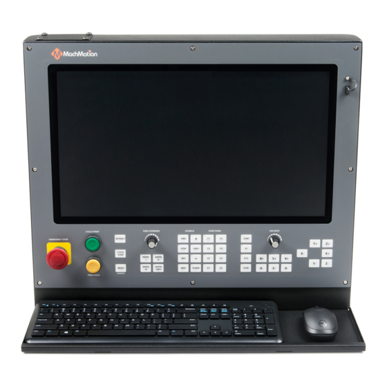
MachMotion 2000 Series General Installation Manual
Hide thumbs
Also See for 2000 Series:
- Manual (7 pages) ,
- Operating manual (34 pages) ,
- Installation manual (140 pages)
Advertisement
Quick Links
2000 Series General Installation
Manual
This installation of a MachMotion control upgrade is the same process no matter what machine type, make or model.
Please use the following manual as your guide to locate and mark the old wiring, remove the original system and install
the new MachMotion complete system. If you need clarification, please contact MachMotion technical support to help
you through the process.
MachMotion Technical Support: (573) 368-7399
Advertisement

Subscribe to Our Youtube Channel
Related Manuals for MachMotion 2000 Series


Summary of Contents for MachMotion 2000 Series
- Page 1 Manual This installation of a MachMotion control upgrade is the same process no matter what machine type, make or model. Please use the following manual as your guide to locate and mark the old wiring, remove the original system and install the new MachMotion complete system.
- Page 2 Mount Back Panel Remove old components 1. Remove everything in the electrical enclosure besides the original transformer. 2. Remove the old cables running to the motors. Mount the new panel 1. Mount the new electrical enclosure to the machine or if you just received a back panel it must be mounted similar to the image below.
- Page 3 (MachMotion Full Cabinet - Apollo III Motion Controller) Mount Control See the 2000 Series Mounting Arm Manual to mount the arm and control. Connect Control and Power Connect Cables to the Control 1. Remove round, rubber plug from the back of the control. Run conduit from the control to the back panel or electrical enclosure 2.
- Page 4 Connect Cables to the Back Panel 1. If using a RapidPath Motion Controller connect the light blue "EtherCAT" cable into N2 on the CTB servo drive.
- Page 5 (RapidPath Motion Controller) 2. Connect the green "Machine Network" cable into the VFD or the network switch. (Yaskawa VFD)
- Page 6 (Apollo III) (Machine Network Switch) 3. Connect the blue "Internet" cable to your local network if you do not plan to use the built in WiFi. Internet is not necessary to run the control. However, assistance from our support team will be greatly limited without access to the internet.
- Page 7 5. For the Yaskawa drive, connect four E-stop cables to the E-10, E-11, E-20 and E-21 blocks as shown below. Note: If you have an additional external E-stop, wire it in series with the control E-stop. You will need to connect your external E-stop into the 24V block and the other side into the blank terminal block.
- Page 8 If possible, take a look at the gears and write down the number of teeth on the motor gear and the ball screw gear. If you write down the gear ratio specifications, ball screw pitch, etc. now, it will make calibration much faster later. (MachMotion Motors)
-
Page 9: Run Cables
Connect Cables to Servo Drives There are several different variations for connecting the motor cables to the servo drives. Please review the schematic that was sent to you by MachMotion. Wire Spindle Motor to VFD There are several different variations for connecting the motor cables to the VFD. Please review the schematic that was... -
Page 10: Wire Inputs And Outputs
Wire Inputs and Outputs Wire any inputs and outputs as shown in the diagrams below. Output Commons Please note, the output common comes pre-jumpered to the 120v circuit to the left of output wiring block as shown below. Verify the voltage of each output destination before wiring. If any of your outputs run on 24VDC, make sure the output common for that output is jumpered to 24V. - Page 11 Wiring Lube System Wiring Coolant System For a contactor with 120VAC coil, wire it as shown.
- Page 12 Note: The contactor shown above is not included. Use the original contactor on your machine. Coolant Pump Power You can power up to a 0.5 hp 3 phase coolant motor. To run a 3 phase motor, the back panel will have to be powered with 3 phase.
- Page 13 Wiring Tool Setter Wiring Probe...
- Page 14 2. Carefully jog each axis. Confirm that they are traveling in the right direction. 3. If a motor is traveling in the wrong direction is can be easily reversed in the MachMotion software. Navigate to the top left of the screen and click Configure>Mach and then click on the Motors.
- Page 15 Configure Software There are several options when configuring the MachMotion software. There is a Knee Mill Setup Wizard for all knee mill controls that are shipped out. For other machine types, review that particular machine type installation manual. Knee Mill Setup Wizard Softlimits It is suggested to go through this part with the machine disabled and to use the handwheels to move the machine.
- Page 16 For each position, you will either need to select Set Softlimit or Skip in order to proceed. As you move through the wizard, the image will change to help you visualize the correct positions. When you set the maximum softlimits for each machine, the control will set your Home position to the same place, unless the machine has previously been homed.
- Page 17 Backlash Some machines will not care about backlash on their axes. In that case, this step may be skipped. Backlash compensation will not completely compensate for all mechanical deficiencies. Be sure to start this wizard with each axis near the middle of travel. The machine needs minimum of 1" of travel in all directions for this wizard to succeed.
- Page 18 For each axis, move the axis negative and then attach a dial indicator and zero it. Then move the axis positive once. Input the error from the indicator and select the direction of error. Then select Calculate & Apply. Verify the backlash by repeating the process until the machine is consistent.
- Page 19 Before the machine is homed or any further setup is completed we must calculate our steps per/unit and calibrate the motors accordingly. MachMotion has a plugin to streamline this process. 1. If you know the gear ratios, ball screw pitch, etc of your machine, use the Automatic Calibration shown here: 1.
- Page 20 Lubrication Pump Your kit is pre-configured with a relay to control the Lube Pump, as seen above. You can change the frequency and duration of which it runs in the MachMotion parameters. Under the Service tab, click the "Interface Config" button.
- Page 21 Then search "Lube" VFD Setup Your Variable Frequency Drive will need to be calibrated for your motor. This can be done directly from the operating software. Under the Service tab, click the "Interface Config" button. Now, search for your VFD. In the search bar (top bar outlined in red below), type in the model that came with your cabinet.
-
Page 22: Additional Documentation
Additional Documentation If you are just setting up your machine and getting used to the 2000 series control, check out these other manuals to learn how to use the Industrial Control and MachMotion Software. For more info on the Control and Operator Panel, check out the "...
Need help?
Do you have a question about the 2000 Series and is the answer not in the manual?
Questions and answers