MachMotion 2000 Series Operating Manual
Hide thumbs
Also See for 2000 Series:
- Manual (7 pages) ,
- General installation manual (22 pages) ,
- Installation manual (140 pages)
Table of Contents
Advertisement
Quick Links
2000 Series RapidPath Operating
Manual
Introduction
RapidPath is MachMotion's EtherCAT motion controller solution. It has integrations for a range of Yaskawa EtherCAT
servo drives, VFDs, the Titanio EverCNC stepper drive, and a subset of the Beckhoff I/O devices. It can be licensed for
up to 64 motors. The control uses a Windows interface to a real time operating system where the EtherCAT master
resides. The operating system is called Intime and the interface is called RapidSetup.
EtherCAT Network Basics
Communication
An EtherCAT network is comprised of a communication master and a series of network nodes. Each millisecond, a
packet of information (known as a frame) is sent from the master to the network and a responding frame is received
back. The frame from the master includes information for each node, such as commanded axis position and outputs.
The frame the master receives back includes feedback position and input status, among many other things.
Limits of increasing the performance of Industrial Ethernet protocols - Scientific Figure on ResearchGate. Available
from: https://www.researchgate.net/figure/EtherCAT-with-100-Mbps_fig4_4304922 [accessed 21 Jan, 2022]
Building a Network
An EtherCAT network is a sequence of devices called nodes. A node is added to the network by plugging an EtherCAT
cable from the out port of one node to the in port of the next node. The in port of the first node is attached to the
EtherCAT port on the back of the control. The out port of the last node will be empty and unconnected. This will create
a chain of devices in order.
I/O couplers will have multiple node items on the network for each coupler. Only the couplers have in and out ports,
but each I/O slice is a distinct node on the network. Some I/O slices that are all 0V connections are not part of the
network. Other example of potential network nodes include servo drives and VFDs.
Regenerating a Network
When there are changes to the network topology due to nodes being added or removed, the communication on the
network will be shut down and the system will have to regenerate. If the machine is running during this time, all
systems will disable. The machine is unable to be enabled while the network is not operational.
If the network has had nodes added to it, the regeneration process will need no interaction from the operator. If the
network has had nodes removed from it, the control will ask if the user wants to override the saved topology and use
the new network. This may result in settings or I/O mappings being lost, as some devices are no longer on the network.
Note that the network does not distinguish unique order of nodes on the network; if you swap the order of two servo
Advertisement
Table of Contents

Related Manuals for MachMotion 2000 Series


Summary of Contents for MachMotion 2000 Series
- Page 1 Manual Introduction RapidPath is MachMotion's EtherCAT motion controller solution. It has integrations for a range of Yaskawa EtherCAT servo drives, VFDs, the Titanio EverCNC stepper drive, and a subset of the Beckhoff I/O devices. It can be licensed for up to 64 motors. The control uses a Windows interface to a real time operating system where the EtherCAT master resides.
-
Page 2: Axis Configuration
drives, control settings will not move with the original devices and may create unexpected motion. Configuration Overview All configuration must be done while the machine is disabled. Axis Configuration Connecting Axes An axis is added to the network by plugging an EtherCAT cable from the out port of one node to the in port of the new servo node. - Page 3 After motors are enabled, they can be assigned to axes. An axis must have one master motor and can support up to five slave motors. 1. On the menu bar, click Configure -> Control, then select the Axis Mapping tab. 2.
- Page 4 The machine can now run motion, but units and direction have not yet been calibrated. Use extreme caution when moving the machine. Motor Direction, Velocity, and Acceleration Motor Direction By default, the control will assume that moving an axis in the positive direction is done by turning it's motors in the positive direction.
- Page 5 Manual Unit Calibration Manual unit calibration does not require any knowledge of the machine mechanics, but does require an accurate way to measure distance moved by an axis. 1. On the menu bar, click Configure -> Plugins -> Machine Calibration , then select Manual Calibration. 2.
- Page 6 Manual Unit Adjustment The units for individual motors can be manually adjusted in the control configuration on the motors tab. This is not recommended for normal calibration. If the units are manually adjusted here, also adjust them to match on the Auxiliary Positions tab.
-
Page 7: Drive Parameters
At this point, axes should have correct motion with accurate units and reasonable speeds and accelerations. The machine has not been homed and limits have not been set up. Use caution while moving the machine. Drive Parameters Drive parameters are directly editable from the control software without any additional cables. 1. -
Page 8: Home Status
Homing RapidPath supports a variety of homing methods. The exact methods available will depend on the capabilities of your drives. Units must be set up and accurate before doing any homing operations. If limit switches are to be used on your machine, it is recommended to set those up before homing. See Limit Switches. - Page 9 3. Each motor on the axis will move to it's end position. 4. The axis will wait for all motors to be done and then report homed. General Homing Setup All axes must know which direction to travel in order to find their home position, the speed at which to travel at, the offset from the marker to call their home position, and the order in which all axes home.
- Page 10 2. Select the motor that you need to change by selecting it from the list on the left side. 3. Choose the desired homing method from the drop down labeled Homing Method. Home to Current Position Home to current position does not move the motor in any direction. It will call it's current location the home position. This method is most often used with absolute encoders as repeatability can be difficult.
-
Page 11: Absolute Encoders
Absolute Encoders Absolute encoders can be enabled per motor. They must be enabled on the motion controller level and in the drive parameters. 1. On the menu bar, click Configure -> Plugins -> RapidPath, then select the Drives tab. 2. Select the motor that you need to change by selecting it from the list on the left side. 3. -
Page 12: Soft Limits
First Homing Homing should now be completely set up. Home each axis individually to verify the configuration. Press the Home All button again to make sure everything works correctly. If homing is incorrectly configured, the machine could crash. Be prepared to trigger Emergency Stop until configuration is verified. - Page 13 1. Home the machine. 2. Change the position DROs to Machine Coordinates. This is indicated by them being orange. Part coordinates (defined by G54) are shown in gray. 3. For each axis, jog the machine to one extent of travel and record the machine coordinate at that point. 4.
- Page 14 At this point, the machine is safe to move while soft limits are active. I/O Configuration Beckhoff I/O Naming Convention All I/O points on the system are identified by their device and name. The device will indicate the physical component the I/O is a part of and the name will indicate which terminal on the device corresponds to the I/O point.
- Page 15 Limit Switches Each motor has a limit switch signal for positive and negative overtravel. These signals must be enabled and mapped to the appropriate I/O point to work. The signals are called Motor # ++ and Motor # --, where # is the motor number. The I/O point that is mapped here needs to be the one that the limit switch for that motor is wired into.
- Page 16 Home Switches Each motor has a home signal for use during homing. If a motor is not using the Home to Switch method, then it's signal does not need to be configured. The home signal for a motor is called Motor # Home, where # is the motor number.
- Page 17 Assigning I/O to Output Signals There are 64 general purpose outputs available for use. 1. On the menu bar, click Configure -> Control, then select the Output Signals tab. 2. Scroll to the signal you want to map an I/O point to. 3.
- Page 18 Mist and Coolant Control Many machines utilize mist and coolant outputs on the machine. The output signals for them are called Coolant On and Mist On. They can be controlled in gcode files with M07 (mist) and M08 (coolant), with M09 turning both outputs off.
- Page 19 Calculating Analog Scaling The Numerator, Denominator, and Offset values associated with an analog signal all deal scaling the user values of the I/O point to the physical values of the I/O point. Analog values are represented by a certain number of bits, which is often unwieldy for user use.
- Page 20 Denominator Lower Denominator Upper Beckhoff Slice Type Bit Width Denominator Value Value Value EL4034 -65535 65535 131070 EL3002 -65535 65535 131070 Probing RapidPath supports up to ten probe signals. The probe signals should be mapped to the corresponding I/O point in the control configuration.
- Page 21 Verifying Signal Mapping All enabled signals can be seen on the main screen by going to the Service -> Machine I/O page. There will be a list of enabled input signals, a list of enabled output signals, and a list of I/O points. The input signals and output signals will be populated automatically from all enabled signals in the configuration window.
- Page 22 Using Signals In Gcode The 64 general purpose output signals can be controlled from gcode using the mcodes M220 and M221. The gcode can wait on one of the 64 general purpose inputs to be a certain state with mcode M222. For more information, refer to the Mach4 Advanced M-Code Reference manual.
- Page 23 Servo Spindle as Main Spindle 1. On the menu bar, click Configure -> Plugins -> RapidPath, then select the Drives tab. 2. Select the motor that will be the servo spindle by selecting it from the list on the left side. 3.
-
Page 24: Analog Spindle
Servo Spindle as Auxiliary Spindle There are multiple types of auxiliary spindles available, depending on your machine type. The servo spindle must first be told it is an auxiliary spindle, and then it can be mapped to an available type. See Auxiliary Spindles below for further instructions. -
Page 25: Device Identification
For +/- analog controlled spindles: 1. On the menu bar, click Configure -> Control, then select the Output Signals tab. 2. Enable the Spindle On signal. 3. Map the appropriate digital output to the signal. 4. Press Apply to save any changes and OK to close the configuration window. For 0-10V analog controlled spindles: 1. -
Page 26: Troubleshooting
9. Map During Speed Agree to the Spindle At Speed signal. 10. Map During Zero Speed to the Spindle At Zero signal. 11. Select the Output Signals tab. 12. Enable the Spindle Fwd and the Spindle Rev signals. 13. The device name for both signals will be the same name that was in the RapidPath VFDs device list. 14. - Page 27 1. On the menu bar, click Configure -> Plugins -> MachMotion, then select the Parameters tab. 2. Go to the Subspindle section. 3. Set the Sub Spindle Enabled parameter to Yes. 4. Set the Sub Spindle Accel Time appropriately for your VFD.
- Page 28 5. Press Apply to save any changes and OK to close the configuration window. 6. On the menu bar, click Configure -> Plugins -> MachMotion, then select the Parameters tab. 7. Go to the Grind Wheel (1) section.
- Page 29 5. Press Apply to save any changes and OK to close the configuration window. 6. On the menu bar, click Configure -> Plugins -> MachMotion, then select the Parameters tab. 7. Go to the Regulating Wheel (1) section.
-
Page 30: Additional Configuration
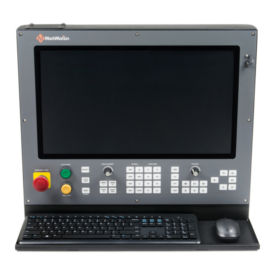
14. Set the Regulating Wheel Bearing Limit parameter appropriately for the machine mechanics. 15. Set the Regulating Wheel Speed Register parameter. 1. Double-click the value field to open a selector window. 2. Select Register for the type field. 3. Select the name of your device for the second field. 4. - Page 31 Operator Panel Function Buttons The 2000 Series operator panels and the wireless pendants have up to eight configurable function buttons available. These buttons can be assigned to predefined options. Not all options will exist on all systems. If you have a functionality need that does not exist on the machine, call MachMotion.
-
Page 32: Network Diagnostics
Network I/O The first page in diagnostics shows all I/O points on the network, split by device and approximate layout. This is updated live with the actual I/O states. Double-clicking on an output will change the state of the I/O. Manually activating I/O can have unexpected results on the machine and control. -
Page 33: Device Functions
This page has a Reset Absolute Encoder button that will do this functionality. It will cause the network to regenerate afterwards. Warranty Information MachMotion warranty policy is subject to change. Updated information is available at our website: https://machmotion.com/warranty The MachMotion Team http://www.machmotion.com...
Need help?
Do you have a question about the 2000 Series and is the answer not in the manual?
Questions and answers