Table of Contents
Advertisement
Quick Links
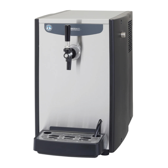
商用生啤机
DRAFT BEER DISPENSER
使用说明书
INSTRUCTION MANUAL
● 使用说明书是本产品不可分割的重要组成部分,用户须妥善保管。
● 请务必仔细阅读本使用说明书中描述的指南和警告事项,因为这些指南和警告事项
为安装人员/用户提供了正确安装、持续安全地使用和保养本产品所需的重要信息。
● 请妥善保管本使用说明书,以便必要时参考使用。
● This booklet is an integral and essential part of the product and should be kept
and preserved by the user.
● Please read carefully the guidelines and warnings contained herein as they are
intended to provide the installer/user with essential information for the proper
installation and the continued safe use and maintenance of the product.
● Please preserve this booklet for any further consultation that may be necessary.
生产商:
Manufacturer:
DBF-40SAC
DBF-40SAC
DBF-25SAC
L1B074304 (011518)
Advertisement
Table of Contents

Subscribe to Our Youtube Channel
Related Manuals for Hoshizaki DBF-40SAC


Summary of Contents for Hoshizaki DBF-40SAC
- Page 1 商用生啤机 DBF-40SAC DBF-25SAC DRAFT BEER DISPENSER 使用说明书 INSTRUCTION MANUAL DBF-40SAC ● 使用说明书是本产品不可分割的重要组成部分,用户须妥善保管。 ● 请务必仔细阅读本使用说明书中描述的指南和警告事项,因为这些指南和警告事项 为安装人员/用户提供了正确安装、持续安全地使用和保养本产品所需的重要信息。 ● 请妥善保管本使用说明书,以便必要时参考使用。 ● This booklet is an integral and essential part of the product and should be kept and preserved by the user. ● Please read carefully the guidelines and warnings contained herein as they are intended to provide the installer/user with essential information for the proper installation and the continued safe use and maintenance of the product.
-
Page 2: Table Of Contents
中文 重要安全须知..............................1 I.. 安装说明..............................2 1.. 构造..............................2 2.. 附件..............................3 3.. 拆包..............................3 . 4.. 位置..............................3. . 5.. 电气连接.............................4 6.. 气体回路与啤酒回路的连接.......................5 [a].CO 气瓶............................6 [b].气压范围............................6 [c].外部CO 气管. - Page 3 ENGLISH IMPORTANT SAFETY INFORMATION ....................17 I. INSTALLATION INSTRUCTIONS ....................18 1. CONSTRUCTION ........................18 2. ACCESSORIES ..........................19 3. UNPACKING ..........................19 4. LOCATION ..........................19 5. ELECTRICAL CONNECTIONS ....................20 6. GAS AND BEER CIRCUIT CONNECTIONS ................21 [a] CO2 GAS CYLINDER ......................22 [b] PRESSURE RANGE ......................22 [c] EXTERNAL CO2 GAS LINE ....................22 [d] EXTERNAL BEER LINE ......................23 7.
-
Page 4: 重要安全须知
中文 重要安全须知 本说明书提供可能导致死亡、严重受伤或损坏设备的注意事项,请用户使用时注意。 警告 表示如不避免,则可能导致死亡或严重受伤的危险情况。 小心 表示如不避免,则可能导致轻微受伤或中度受伤的危险情况。 注意 表示如不避免,则可能导致本设备损坏的危险情况。 卫生 表示与卫生和食品安全相关的重要预防措施。 重要 表示与使用和维护本设备相关的重要信息。 警告 本产品为生啤机,只能用于本机所明确设计的用途。 其它任何用途都被视为不当用途,因而可能造成危险。对因本产品使用不当、使用不正确和不合理所造成的的任何损失,生产商 不承担法律责任或相关责任。 安装及必要时的移机作业,必须交由具备相应知识的作业人员依照现行法规并根据生产商的说明进行。 保持机体内外通风口畅通无阻。 使用任何电气设备均应遵循一些基本规则,尤其是 : * 高湿度和潮气会加大电路短路及潜在触电的危险。如有可疑情况,请切断生啤机电源。 * 将生啤机与供电网络断开时,请勿损坏或拉扯电源线。 * 请勿用湿手触碰电气部件或操作开关。 * 本产品不适合残障、智障及缺乏相应经验和知识的人士 ( 包括儿童 ) 单独使用,除非有专人负责其安全,并对其使用本产品加 以监督和指导。 * 另外还应对幼童加以看管,以确保其不玩耍本产品。 * 请勿尝试改装生啤机。应仅由具备相应知识的作业人员实施拆解或维修作业。... -
Page 5: 安装说明
中文 I. 安装说明 1. 构造 [13] [13] [12] [12] [11] [11] [10] [10] DBF-40SAC DBF-25SAC [1] 搅拌装置马达 用于搅拌水箱中的冷却水,以有效冷却啤酒,其位于顶盖板下方。 [2] 水箱 为啤酒冷却水制冰。 [3] 管接螺母 [4] 啤酒龙头 将啤酒注入杯中。 [5] 格栅(附件) [6] 排水盘 (附件) [7] 排水口 将冷却水从水箱中排出。插入橡皮塞即可关闭排水口。 [8] 溢流软管 使水箱中的冷却水保持在恒定水位。 [9] 铭牌 [10] 啤酒进口... - Page 6 中文 [11] 机械室 含制冷回路和电气部件。 [12] 顶盖板 [13] 顶板 2. 附件 使用说明书 刷子 清洁海绵 刷子(S) 扳手 说明书 刷子 清洁海绵 刷子(S) 扳手 挂钩 挂钩安装螺钉 链条 排水盘 挂钩 挂钩安装螺钉 链条 排水盘 格栅 格栅 喷口盖 O形圈 P021 啤酒龙头 啤酒配适器 (仅DBF-25SAC) 喷口盖 O形圈P021 啤酒龙头 啤酒配适器 3.
-
Page 7: 电气连接
中文 小心 生啤机应安装在坚固和平坦的地面。 注意 请勿在通风窗前放置任何物品,以免将其堵塞。 重要 正常工作的环境温度应为5℃~35℃,冷却水温度应为5℃~30℃,啤酒桶温度应为10℃~30℃。如果生啤机长时间超出上述正 常温度范围工作,可能会影响其工作能力。 请勿将本机安装在可能会结冰的场所。 必须留出指定的空间,以确保通风顺畅和便于维修保养。 后 左 右 高湿度环境下, 机器内部可能会产生冷凝水, 进而滴在地板上。 因此, 请勿将其安装在易因滴水而损坏地板的场所。 5. 电气连接 警告 本机必须接地 本产品必须按所在国家和地区的电气安全标准进行接地。 为避免造成人体触电或设备严重受损,请在生啤机上正确地连接地线。 进行任何保养、维修或清洁作业前,请将电源插头从插座中拔出。 * 本机需使用单独的电源(220~240VAC/10A),而且必须采用合适的断路器保护电源。 * 主控制箱保险丝的额定电流为10A,必须交由具备相应知识的维修人员进行更换。 * 通常情况下,应由持有电工资质证书或经授权的维修人员进行作业。 * 如果电源线和/或插头需要更换,只能由专业的售后工程师进行更换。... - Page 8 中文 6. 气体和啤酒回路的连接 重要 为便于出售桶装扎啤,请根据以下说明准备并安装下列设备。 [13] [12] [11] DBF-40SAC DBF-25SAC [10] [1] 气体软管快接接头 (调节器侧) [2] 啤酒桶连接器 用于引出桶中的啤酒。请咨询酒类专卖店或啤酒公司,以便为酒桶配置合适的连接器。 [3] 啤酒软管快接接头(连接器侧) [4] 啤酒软管快接接头(生啤机侧) [5] 啤酒软管 [6] 气体软管快接接头 (连接器侧) [7] 清洗罐 [8] 啤酒桶 [9] 气体软管 [10] CO 气瓶 内含CO 气体,可防止啤酒走气,并通过气体压力将啤酒压出。请咨询酒类专卖店或啤酒公司,以便配置合适的CO 气瓶。 [11] 瓶链(附件) 将CO 气瓶牢靠地固定在安装好的挂钩上。 [12] 挂钩(附件) 请使用随附的螺钉将其安装到稳固的地方。 [13] 调节器 调节气瓶中的CO 气压,以便啤酒流出。请咨询酒类专卖店或啤酒公司,以便配置所需的调节器。...
-
Page 9: [A].Co 2 气瓶
中文 [a] CO 气瓶 警告 请小心地对调节器进行操作以免其遭受冲击,否则压力表准确度将受到影响。 请使CO 气瓶保持竖直状态,并用链条附件将其牢靠地固定住。 请确保CO 气瓶远离直射阳光和40℃以上的高温。 水平仪 主阀 1) 将新CO 气瓶的主阀打开片刻,以吹除接头处的污物和灰尘。 螺母 注:请保持脸部远离气瓶。 啤酒调节器 2) 检查调节器垫片。若垫片出现移位或受损,可能导致气体泄漏。 调节旋钮 3) 将调节器安装到CO 气瓶上。将螺母紧固至8 Nm扭矩,以使水平仪保持垂直。 4) 打开主阀并(根据有无气息声)检查螺母是否漏气。若发生漏气,请重新紧固螺母。 5) 完成连接后,转动调节旋钮,确保气压处于下表所示的范围内。 衬垫 [b] 气压范围 将CO 的气压调节到以下范围(参考值)。 * 调节器设计因各啤酒公司而异。 啤酒桶温度 气压 10℃ 0.15 ~ 0.20 MPa ( 刻度 : 1.5 ~ 2.0) 20℃ 0.22 ~ 0.25 MPa ( 刻度 : 2.2 ~ 2.5) 30℃... -
Page 10: [D].外部啤酒管
3) 切割啤酒软管时,确保切割面垂直。 4) 将啤酒管插入啤酒入口连接器的快速接头上。用力拉拽软管,以检查其连接是否紧固。 7. 试运转 [a] 如何制备冷却水 重要 填充水箱前请仔细阅读下文。 水箱冷却水的电导率(E.C.) 请勿使用自来水。 请将E.C.在100~300μS/cm范围内的水注入水箱。 请用电导仪测量电导率。 * E .C.:一种物理属性,表示物质的导电能力。 单位:μS(微西门子)/cm 100μS/cm以下: 压缩机可能无法正常工作,导致冷却性能严重下降。 300 μS/cm以上: 蒸发器上可能会聚集过多的冰,导致啤酒在啤酒盘管内冻结,使机器无法正常出酒。 如何制备电导率在100~300μS/cm范围内的冷却水 冷却水箱容量约为16L(DBF-40SAC)/10L(DBF-25SAC)。 冷却水的制作:将3g(DBF-40SAC)/2g(DBF-25SAC)纯小苏打溶入16L/10L蒸馏水中。 步骤1 喷口盖1/2(3g) 用喷口盖(附件)量取3g/2g纯小苏打。 泡沫喷口盖(1g) 1/3(2g) 喷口盖 步骤2 将约16L/10L蒸馏水注入桶中,加入步骤1中量取的3g/2g小苏打后,然后充分搅拌。 若要测量电导率,请使用电导仪。 蒸馏水 使用后请冲洗喷口盖。 (约16L/10L) 桶 [b] 冷却水供应 警告 拆下顶板时,请勿触碰前板或钢丝冷凝器的边缘,以免受伤。... -
Page 11: [C].安装后的检查
中文 1) 确保本机的电源插头未接通电源。 2) 拆下顶板。 3) 将冷却水加注到水箱中的标准水位标记处。 4) 装回顶板。 5) 插入本机的电源插头。 [c] 安装后的检查 小心 拆卸顶板进行清洁或检查作业前,请务必拔下本机的电源插头。 * 运输前已清洁过啤酒回路。但首次开机前请再次清洁该回路,并检查各部件是否安装正确。 * 开机前请检查电源线和软管。 II. 操作说明 1. 操作前的检查(每天) [a] CO 气瓶的检查和更换 警告 搬运CO 气瓶时请勿晃动,并确保已盖上盖子。 1) 关闭CO 气瓶的主阀。 2) 将调节器调节至“0”。 3) 从空的CO 气瓶上拆下调节器并盖上盖子。 4) 请遵循“I. 6. [a] CO 气瓶”中的步骤1)~4)。 [b] 啤酒桶的检查和更换 警告 请勿松开桶上的套圈。 重要 为防止产生过多泡沫,请勿滚动或摇动啤酒桶。操作时请务必小心。 啤酒桶将空时会产生较多泡沫。此时,应尽快更换为新桶。 啤酒桶完全变空时,啤酒龙头中会喷出CO2气体和啤酒沫。 请勿将已打开的啤酒桶储存在冷柜中。确保储存温度在30℃以下。 必要时,请用水清洗桶接头。 桶连接器把手 1) 关闭啤酒回路。... -
Page 12: [A].啤酒龙头操作
中文 2) 将调节器旋钮逆时针转动至“0”。 调节器 调节旋钮 桶连接器 3) 逆时针转动桶连接器,并将其从桶上拆下。 桶 旋转型 垂直型 桶连接器 4) 通过顺时针转动将桶连接器安装至新桶上。 桶 旋转型 垂直型 调节器 调节旋钮 5) 顺时针转动调节器旋钮,将气压调节到啤酒公司规定的水平。 桶连接器把手 6) 打开啤酒回路。 旋 转 型 : 顺 时 针 转 动 桶 连 接 器 把 手,直至无法转动。 垂直型:向下按压桶连接器把手, 直至其锁定到位。 旋转型 垂直型 7) 出酒前,需根据“2. [b] 将啤酒引至龙头”所述内容将啤酒引至啤酒龙头处。 2. 出酒 啤酒龙头拨杆... -
Page 13: [B].将啤酒引至龙头
中文 [b] 将啤酒引至龙头 重要 请及时倒掉排水盘中的水和啤酒。吸收空气中的潮气后,水箱中的冷却水会增多,过多的冷却水会通过溢流软管流入排水盘。若 不及时倒掉,水会从排水盘溢出到地板上。 1) 检查调节器旋钮,确保气压已调节到啤酒公司规定的水平。 2) 检查并确保啤酒龙头拨杆已关闭。在啤酒龙头拨杆打开的情况下打开桶连接器,会导致啤酒喷出。 3) 打开桶连接器。 4) 用杯子盛接啤酒,并用力将啤酒龙头拨杆向后推动(出沫位置)。保持推压状态可出沫。当泡沫达到杯子的一半位置时,将拨杆 移至原位以停止出沫。 5) 步骤4)后至少等待1分钟,以使啤酒在回路中保持稳定状态。 6) 放置另一个杯子,将啤酒龙头拨杆朝外拉动以出酒。保持出酒状态,直至泡沫变为液体。 7) 检查桶连接器、桶连接处和啤酒软管接头是否漏酒。 [c] 出酒 重要 若啤酒回路未经冲洗且啤酒龙头中有残余啤酒,阀轴可能会从内部堵塞啤酒龙头,导致无法出酒、出酒不畅或无法停止出酒。这 种情况下,请根据“III.5. 啤酒龙头的拆解和清洁 ( 每周 )” 5. 对啤酒龙头进行拆解和清洁。 1) 将一个干净的杯子倾斜45°,使其内表面接触到啤酒龙头的啤酒喷口。 2) 向外拉动啤酒龙头拨杆,使啤酒沿着内表面流入杯中。 3) 盛接一定量的啤酒后,将啤酒龙头拨杆移回原位,以停止出酒。 4) 若要添加泡沫,则向后推动啤酒龙头拨杆。保持推压拨杆时,泡沫会不断从 啤酒龙头的泡沫喷口中涌出。停止出沫时,请将拨杆移回原位。 [d] 操作结束 重要 为防止桶装扎啤中混入过多的 CO 气体,请确保操作结束时关闭 CO 气瓶的主阀。 喷口盖附件可保护啤酒龙头喷口在闲置时远离灰尘或昆虫。操作结束时请务必盖上喷口。 啤酒桶上的桶连接器关闭时,气体可能残留在啤酒回路中。为防止泡沫过多或出酒不畅,请在第二天开始操作前将啤酒引入啤酒 回路,直到其中的气体完全从啤酒龙头中排出。... -
Page 14: 啤酒回路(每天)
中文 1) 关闭桶连接器,并将其从桶上拆下。根据“III. 1. 啤酒回路(每天)”和“III. 4. 用海绵清 洁啤酒回路(每周)”冲洗啤酒回路。 啤酒龙头 2) 将调节器旋钮逆时针转动至“0”。 3) 顺时针转动主阀,关闭CO 气瓶。 4) 将喷口端部擦干。请将喷口盖清洗干净,并将其安装到喷口上。设备运行期间,请将 喷口 喷嘴盖保存在干净的地方。 喷口盖 装上 III. 保养 重要 操作结束后,请务必采取以下保养措施。 必要时,请参照以下的保养说明进行操作。 在温水(30~40℃)中加入10ml浓度为10%的逆化皂(氯化苯), 即可配制出所需的消毒剂。 使用消毒剂前, 请仔细阅读说明。 注意 请不要在清洁操作中丢失任何部件,否则机器将漏水或无法正确出酒。 为防止表面的塑料材质受损, 请勿使用稀释剂、 挥发油、 石油精、 肥皂粉、 抛光粉、 碱性洗涤剂和硬毛刷, 而风扇及灶具去污粉更应禁止 使用。 同样, 为防止材料被腐蚀, 请勿使用含氯漂白剂。 卫生 请务必保持双手洁净,并使用干净的抹布实施清洁作业。 1. 啤酒回路(每天) 重要 请使用啤酒公司规定的清洗罐。请遵循清洗罐上的操作说明。... -
Page 15: 啤酒龙头(每天)
中文 11) 打开啤酒回路。 旋转型:顺时针转动桶连接器把手,直至无法转动。 垂直型:向下按压桶连接器把手,直至其锁定到位。 注: 若 清洗罐内部有虹吸管,放置清洗罐时套圈端朝上;若清洗罐内部无虹吸管,放置清洗罐时套圈端朝下。 桶连接器把手 虹吸管 旋转型 垂直型 有 无 12) 准备用于盛放清洁水的塑料桶。向外拉动啤酒龙头拨杆,进行出水 操作。当啤酒变为水时,向后推动拨杆,以冲洗泡沫回路。 桶 13) 水不再流出时,将调节器旋钮逆时针转动至“0”。使啤酒龙头处于 打开状态。顺时针转动主阀,关闭CO 气瓶。气体不再流出时,将啤 酒龙头拨杆拉回原位,以关闭啤酒龙头。 14) 关闭啤酒回路。 桶连接器把手 旋转型:逆时针转动桶连接器把手,直至无 法转动。 垂直型:解锁并完全提起桶连接器把手。 旋转型 垂直型 桶连接器 15) 逆时针转动桶连接器,并将其从清洗罐上拆下。 16) 将桶连接器顺时针转到底,以将其连接至桶上。 17) 彻底清洁清洗罐,并妥善干燥,随后盖上盖子,以免灰尘进入。 18) 将啤酒龙头喷口擦干。请将喷口盖清洗干净,并将其安装到喷口上。设备运 清洗罐 行期间,请将喷嘴盖保存在干净的地方。 旋转型 垂直型 2. 啤酒龙头(每天) 松开(顺时针) 1) 顺时针转动啤酒龙头的管接螺母,并将啤酒龙头拆下。 管接螺母... -
Page 16: 排水盘(每天)
中文 3. 排水盘(每天) 将抹布浸入含逆化皂的温水(30~40℃)中,然后用抹布擦拭排水盘表面。 3分钟后,用含有冷水或温水的干净抹布擦除剩余的肥皂。必要时,请清 洁排水盘。 溢流软管通孔 1) 拆下格栅并提起排水盘,使安装孔脱离安装螺钉。请注意勿使其中的 水和啤酒溢出。 2) 倒掉水和啤酒,并用自来水清洗格栅和排水盘。 格栅 3) 提起排水盘,使安装孔钩住安装螺钉,并将格栅安装到排水盘上。 安装螺钉 4) 确保溢流软管穿过格栅中的孔,并可将水排至排水盘中。 排水盘 溢流软管 4. 用海绵清洁啤酒回路(每周) 重要 妥善保管使用过的清洁海绵,供以后使用。 请使用啤酒公司规定的清洗罐。请遵循清洗罐上的操作说明。 使用随附的清洁海绵。为防止堵塞,请勿使用一块以上的海绵或其他海绵。 1) 冲洗前请关闭啤酒回路。 旋转型:逆时针转动桶连接器把手。 垂直型:解锁并完全提起桶连接器把手。 2) 将调节器旋钮逆时针转动至“0”。 3) 顺时针转动主阀,关闭CO 气瓶。 4) 向外拉动啤酒龙头拨杆,以出空回路中剩余的啤酒。 5) 啤酒不再流出时,将拨杆移回原位。 啤酒龙头拨杆 6) 顺时针转动啤酒龙头的管接螺母,并将啤酒龙头拆下。 盖形螺母 7) 拧松啤酒龙头的盖螺母,并拆解啤酒龙头。按照图示沿相反方向安装阀轴,并 紧固盖螺母。(防止清洁海绵堵塞啤酒龙头。) 阀轴 8) 紧固管接螺母,将啤酒龙头安装至机器上。 9) 在啤酒龙头下放置塑料桶,用于盛接排出来的水。 10) 请彻底清洁清洗罐,并充注自来水。 阀轴 11) 从桶连接器上拆下啤酒软管快接接头,将一块(仅一块)清洁海绵放入接头中,并将... -
Page 17: 啤酒龙头的拆解和清洁(每周)
中文 15) 清洁海绵会连水一起从接头中出来。 清洁海绵 16) 清洁海绵和水出来时,将调节器旋钮逆时针转动至“0”。关闭CO 气 瓶的主阀。等待直到气体停止从啤酒龙头中流出。 阀轴 17) 关闭啤酒回路。 旋转型:逆时针转动桶连接器把手。 桶 垂直型:解锁并完全提起桶连接器把手。 18) 逆时针转动桶连接器,并将其从清洗罐上拆下。 19) 从水桶中取出清洁海绵。 20) 重复步骤10)~16),直至啤酒龙头中流出干净的水。 槽孔 阀轴 21) 拆下啤酒龙头,将阀轴置于正常位置,并将啤酒龙头装回生啤机上。 22) 将桶连接器连接至桶上。 23) 用自来水彻底清洗清洁海绵。排干海绵中的水,并将其妥善保管,供以后使用。 5. 啤酒龙头的拆解和清洁(每周) 1) 冲洗前请关闭啤酒回路。 旋转型:逆时针转动桶连接器把手。 垂直型:解锁并完全提起桶连接器把手。 2) 将调节器旋钮逆时针转动至“0”。 3) 向外拉动啤酒龙头拨杆,以出空回路中剩余的啤酒。顺时针转动啤酒龙头的管接螺母,并将啤酒龙头拆下。 拨杆 4) 拧松啤酒龙头的盖螺母并拆下拨杆。 盖形螺母 5) 从啤酒龙头上拆下阀轴。 阀轴 6) 使用中性餐具洗涤剂和清洁刷(附件)清洁啤酒龙头和阀轴。 7) 使用刷子(S)(附件)清洁啤酒龙头上的两个小孔。 阀轴 刷子(S) 阀轴 啤酒龙头横截面... -
Page 18: 桶连接器(每周)
中文 8) 用清水彻底冲洗啤酒龙头。 9) 通过阀轴上的孔(较大的孔朝上)正确组装啤酒龙头。 6. 桶连接器(每周) 请根据啤酒公司的说明书清洁桶连接器。 7. 外壳(每周) 不锈钢外壳同样需要清洁,以防发生腐蚀。请用软布擦拭。使用含中性餐具洗涤剂的湿软布擦除积聚的污垢,随后擦除残留的洗 涤剂。必要时,请清洁外壳。 8. 钢丝冷凝器(每半年) 钢丝冷凝器位于设备后部,请用真空吸尘器或牙刷除去上面的污垢和灰尘。 IV. 检查 1. 气体软管和啤酒软管(每月) 检查气体软管和啤酒软管是否损坏、变形和漏水(有无污点)。如果发现故障,请联系授权的星崎维修公司。 2. 连接插头和电源线(每年/每半年) 警告 请定期检查并确认连接插头极片及其周围无灰尘积聚,且连接插头已切实插入插座中。极片带尘或连接松动可能会造成触电或火 灾事故。 请勿损坏电源线,即严禁对电源线进行二次加工,或过分用力拉扯、捆扎、按压或卡住电源线,否则会造成触电或火灾。 本机必须采用独立电源供电。请勿设置分支电源线、使用电源延长线或与其它设备共用一个电源,否则可能会导致触电、发热或 火灾。 请检查: * 连接插头极片及其邻近部位和电源插座上无灰尘积聚。必要时应进行清洁。 * 插头和电源线附件未受损,并且未处于受压或卡住的状态。 * 连接插头对应单独的电源插座。 3. 冷却水(每半年) 重要 一年更换两次冷却水。 拔排水塞时,不能拔链条,直接拔排水塞。 1) 拔掉机器插头。 2) 拆下顶板。 3) 检查冷却水位是否到达水箱上的标准水位标记。若水量不足,则用冷却水加注水箱。 冷却水的更换步骤: 4) 拆下排水盘。... -
Page 19: 其它信息
1. 长时间不使用生啤机时 * 在关闭本机超过一周的情况下,请执行以下保养程序,以清洁和排空啤酒回路并保持机器洁净: III. 4. 用海绵清洁啤酒回路 5. 啤酒龙头的拆解和清洁 6. 桶连接器 7. 外壳 * 根据“IV. 3. 冷却水”排空水箱。可能需要数日才能融化水箱中的冰。待所有冰融化后,再次排空水箱并干燥水箱内部。 2. 移机、废弃处理、运输 * 若要实施移机作业或弃置本产品,请联系星崎授权的维修公司。 * 销售和移交本机时,请用胶带将本使用手册粘附在本机外部,以便为新用户提供有关安全、正确使用本机的重要信息。 3. 保修 星崎向原始拥有者/用户保证,所有星崎品牌产品在产品“保修期”内不存在材料和/或工艺缺陷。产品保修在自产品安装之日起 一年内有效。 星崎在此保修条款下承担有限责任,日常维护、清洁、必需的保养和/或因误用以及未根据星崎的准则安装而导致的修理则不在星 崎的责任范围内。 保修范围内的维修应由授权的星崎经销商或维修机构采用星崎的原装/纯正零部件实施。 若要获取有关保修和授权维修机构的详细信息,请联系经销商/供货商或最近的星崎维修办事处: 规格 型号 DBF-40SAC DBF-25SAC 电源 单相220V 50Hz 单相220-240V 50Hz 出酒量 40 L (30℃ ~ 8℃ / 4小时) 25 L (30℃ ~ 8℃ / 4小时) 制冰时间 8小时(初始冷却水温度:30℃) 5小时(初始冷却水温度:30℃) 储冰量 尺寸 330mm(宽) x 646mm(深) x 510mm(高) 255mm(宽) x 578mm(深) x 460mm(高) 冷媒 R134a、120g R134a、95g 重量... - Page 20 (Cr(Ⅵ)) (PBB) (PBDE) 填充阀 制冰机全型号、冰箱全型号、啤酒机 × ○ ○ ○ ○ ○ 拨动开关 制冰机(KMD-270AA;KMD-270AWA) × ○ × ○ ○ ○ 电源线 啤酒机(DBF-40SAC;DBF-25SAC) × ○ ○ ○ ○ ○ 供电板 冰箱(HRE-*B;HFE-*B;HRFE-*B) × ○ ○ ○ ○ ○ 冰箱(HRE-*B;HFE-*B;HRFE-*B) 风扇马达 × ○ ○...
- Page 21 ENGLISH IMPORTANT SAFETY INFORMATION Throughout this manual, notices appear to bring your attention to situations which could result in death, serious injury, or damage to the unit. WARNING Indicates a hazardous situation which, if not avoided, could result in death or serious injury. CAUTION Indicates a hazardous situation which, if not avoided, could result in minor or moderate injury.
-
Page 22: Installation Instructions
[12] [12] [11] [11] [10] [10] DBF-40SAC DBF-25SAC [1] Agitator Motor Agitates cooling water in the water tank for effective cooling of beer. Located under the top cover. [2] Water Tank Forms ice for beer cooling water. [3] Union Nut [4] Beer Tap Pours beer into a mug. -
Page 23: Accessories
ENGLISH [11] Machine Compartment Contains refrigeration circuit and electrical components. [12] Top Cover [13] Top Panel 2. ACCESSORIES Instruction Manual Brush Cleaning Sponge Brush (S) Instruction Manual Brush Cleaning Sponge Brush (S) Spanner Spanner Hook Hook Mounting Screw Chain Drain Pan Hook Hook Mounting Screw Chain Drain Pan Grille Grille Nozzle Cap O-Ring P021... -
Page 24: Electrical Connections
ENGLISH CAUTION The location should provide a firm and level foundation for the dispenser. NOTICE Do not place anything to obstruct the ventilation louvers. IMPORTANT Normal operating ambient temperature should be within 5°C to 35°C, cooling water temperature within 5°C to 30°C, and beer keg temperature within 10°C to 30°C. Operation of the dispenser, for extended periods, outside of these normal temperature ranges may affect production capacity. -
Page 25: Gas And Beer Circuit Connections
To sell draft keg beer, prepare and install the following equipment according to the instructions below. [13] [12] [11] DBF-25SAC DBF-40SAC [10] [1] Quick Gas Hose Joint (regulator side) [2] Keg Coupler Dispenses beer out of the keg. Consult with the liquor shop or beer company, and prepare a suitable keg coupler for the keg to be used. -
Page 26: [B] Pressure Range
ENGLISH [a] CO2 GAS CYLINDER WARNING Handle the regulator with care to have no impact on it, or the pressure gauge may not read accurately. Stand the CO2 gas cylinder upright, and fix it securely with the accessory chain. Keep the CO2 gas cylinder away from direct sunlight or temperatures above 40°C. Level Gauge Main Valve 1) Open the main valve of the new CO2 gas cylinder for a second to blow dirt and dust off the joint. -
Page 27: [D] External Beer Line
The capacity of the water tank of this unit is approx. 16 L (DBF-40SAC) / 10 L (DBF-25SAC). Make the cooling water by dissolving 3 g (DBF-40SAC) / 2 g (DBF-25SAC) of pure baking soda in approx. 16 L / 10 L of distilled water. -
Page 28: [C] Checks After Installation
ENGLISH 1) Check that the unit is unplugged. 2) Remove the top panel. 3) Fill the water tank with the cooling water up to the standard water level marked on the tank. 4) Refit the top panel. 5) Plug in the unit. [c] CHECKS AFTER INSTALLATION CAUTION Be sure to unplug the unit before removing the top panel for cleaning or inspection. -
Page 29: Dispensing
ENGLISH 2) Turn the regulator adjust dial counterclockwise to “0”. Regulator Adjust Dial Keg Coupler 3) Turn the keg coupler counterclockwise, and remove it from the keg. Keg Coupler Rotary Type Vertical Type 4) Attach the keg coupler on the new keg by turning it clockwise. -
Page 30: [B] Leading Beer To Tap
ENGLISH [b] LEADING BEER TO TAP IMPORTANT Frequently dump water and beer from the drain pan. The cooling water in the water tank will increase in volume by taking moisture from the air, and come out through the overflow hose into the drain pan. If left as it is, water will flow out of the drain pan onto the floor. 1) Check that the regulator adjust dial is set to the appropriate pressure specified by the beer company. 2) Check that the beer tap lever is closed. Opening the keg coupler with the beer tap lever open will cause beer to splash out. 3) Open the keg coupler. -
Page 31: Maintenance
ENGLISH 1) Close the keg coupler, and remove it from the keg. Flush the beer circuit according to “III. 1. BEER CIRCUIT (DAILY)” and “III. 4. CLEANING BEER CIRCUIT WITH Beer Tap SPONGE (WEEKLY)”. 2) Turn the regulator adjust dial counterclockwise to “0”. 3) Shut off the CO2 gas cylinder by turning the main valve clockwise. Nozzle 4) Wipe moisture from the nozzle end. Wash the nozzle cap clean, and fit it on the Nozzle Cap... -
Page 32: Beer Tap (Daily)
ENGLISH 11) Open the beer circuit. Rotary type: Turn the keg coupler handle clockwise until it stops. Vertical type: Push down the keg coupler handle until it locks in place. Note: If the cleaning tank is provided with a siphon tube, lay the cleaning tank with the ferrule at the top. If not, lay the cleaning tank with the ferrule at the bottom. -
Page 33: Drain Pan (Daily)
ENGLISH 3. DRAIN PAN (DAILY) Wipe the drain pan surfaces by using a cloth containing warm water (30 - 40°C) with invert soap. After 3 minutes, wipe off any remaining soap with a clean cloth containing cold or warm water. Clean the Through Hole for drain pan whenever necessary. -
Page 34: Disassembly And Cleaning Of Beer Tap (Weekly)
ENGLISH 15) The cleaning sponge will come out with water. Cleaning Sponge 16) When the cleaning sponge and water have come out, turn the Valve Shaft regulator adjust dial counterclockwise to “0”. Shut off the main valve of the CO2 gas cylinder. Wait until gas stops flowing out of the beer tap. Bucket 17) Close the beer circuit. -
Page 35: Keg Coupler (Weekly)
IV. INSPECTION 1. GAS HOSE AND BEER HOSE (MONTHLY) Check the gas and beer hoses for damage, deformation, and water leak marks (stains). If any problem is found, contact an authorized Hoshizaki service company. 2. ATTACHMENT PLUG AND POWER CORD (ANNUALLY / BIANNUALLY) WARNING Check periodically that the attachment plug blades and their vicinity are free of dust and that the attachment plug is securely plugged into the receptacle. Dusty blades or loose connection may cause electric shock or fire. -
Page 36: Other Information
3. WARRANTY Hoshizaki warrants to the original owner/user that all Hoshizaki branded products shall be free of defects in material and/or workmanship for the duration of the “warranty period”. The warranty shall be effective for one year from the date of installation. - Page 37 Room 501, Tower 1, Kerry Enterprise Centre, 128 Tianmu Road West, Jing’an District, Shanghai, China 200070 Tel: +86 21 5228-8181 Fax: +86 21 5228-0113 Hoshizaki Hong Kong Co., Limited Unit G, 17/F, World Tech Center, No. 95 How Ming Street, Kwun Tong, Kowloon, Hong Kong Tel: +852 2866-2108...
Need help?
Do you have a question about the DBF-40SAC and is the answer not in the manual?
Questions and answers