Table of Contents
Advertisement
Quick Links
Advertisement
Table of Contents

Subscribe to Our Youtube Channel
Related Manuals for Hoshizaki DBF-AS65WE-EU


Summary of Contents for Hoshizaki DBF-AS65WE-EU
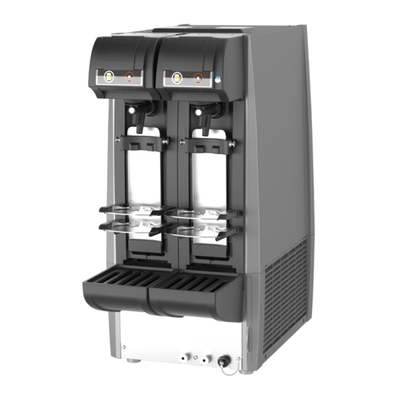
- Page 1 AUTOMATIC DRAFT BEER DISPENSER DBF-AS65WE-EU SERVICE MANUAL B078-1102 (093020)
-
Page 2: Table Of Contents
CONTENTS GENERAL INFORMATION 1. SAFETY INSTRUCTIONS ---------------------------------------------------------------------------- 1, 2 2. CONSTRUCTION --------------------------------------------------------------------------------------------------------- 3 BEER CIRCUIT -------------------------------------------------------------------------------------------------------------- 3 FEATURES ------------------------------------------------------------------------------------------------------------------ 4 3. DIMENSIONS/SPECIFICATIONS --------------------------------------------------------------------------------- 5 (1) DIMENSIONS/SPECIFICATIONS ---------------------------------------------------------------------------------- 5 (2) DISPENSING PERFORMANCE ------------------------------------------------------------------------------------ 6 TECHNICAL INFORMATION 4. UNIT CONTROL ---------------------------------------------------------------------------------------------------------- 7 (1) GENERAL OPERATION ------------------------------------------------------------------------------------------ 7 - 9 5. - Page 3 (21) DISPENSED AMOUNT IS DIFFERENT FROM PRESET AMOUNT (22) MOTOR WILL NOT OPERATE NORMALLY (23) DISPLAY SHOWS ERROR (24) OPERATION PANEL UNIT WILL NOT GO DOWN COMPLETELY (25) OPERATION PANEL UNIT GOES DOWN, BUT DISPENSE BUTTON WILL NOT LIGHT UP WITH “OFF”...
-
Page 4: General Information
GENERAL INFORMATION 1. SAFETY INSTRUCTIONS The following instructions contain important safety precautions and should be strictly observed. The terms used here are defined as follows: WARNING: There is a possibility of death or serious injury to the service person and a third party or the user due to improper service operations or defects in serviced products. - Page 5 (7) Before servicing, check the surface temperature of the refrigeration circuit to prevent a burn. 5. Keep the following in mind when making electrical connections: (1) Check for proper grounding connections, and repair if necessary to prevent electric shocks. (2) Always use service parts intended for the applicable model for replacement of defective parts.
-
Page 6: Construction
2. CONSTRUCTION BEER CIRCUIT Beer Foam Agitator motor Beer coil Evaporator Lever Beer tap Heat exchange Cooling water Regulator (Pressure adjustment) Condenser fan CO2 gas Condenser cylinder Beer Compressor Beer keg Beer dispensing system 1) Beer is delivered from the keg to the unit by CO2 gas pressure. 2) Beer is chilled by going through the beer coil. -
Page 7: Features
FEATURES This unit automatically dispenses a preset amount (time) of liquid or foam when a button is pressed. 1) Automatic dispensing (portion control) is available by a single button operation. 2) Two different mug sizes are available by changing the mug location. 3) Two different mug sizes are automatically detected by changing the mug location. -
Page 8: Dimensions/Specifications
3. DIMENSIONS/SPECIFICATIONS (1) DIMENSIONS/SPECIFICATIONS... -
Page 9: Dispensing Performance
(2) DISPENSING PERFORMANCE Power supply: 220-240V 50Hz Ambient/keg temp: 30°C Gas pressure: 0.35MPa Load: Four 20L beer kegs Mug: 435mL Stop dispensing at 8°C or higher dispensing temp --> Resume dispensing at 1°C or higher water temp Total amount dispensed: approx. 78L 48.3L 10.2L Standby Time... -
Page 10: Technical Information
TECHNICAL INFORMATION 4. UNIT CONTROL (1) GENERAL OPERATION a. Normal operation When the power supply is turned on, one of the lamps on the operation panel lights up and the compressor, condenser fan motor and agitator motor start. • When the ice making sensor (long electrode) detects sufficient ice storage, the compressor and condenser fan motor stop. - Page 11 b. Electrode setting for hard water conditions The electrode setting is adjustable by the setting mode “A05”. c. Condenser fan motor low temperature control When ambient temperature is low, the control ensures ice forming on the evaporator inside the water tank. 1) When ambient temperature is below 10°C (condenser outlet temperature below 13°C), the condenser fan motor stops to raise the condenser temperature to prevent refrigerant liquefaction.
- Page 12 d . Compressor protection when condenser fan motor is locked When the condenser fan motor is locked, the compressor stops to prevent pressure rise in the refrigeration circuit. 1) When the condenser fan motor is locked during operation and the condenser outlet temperature reaches 75°C, the compressor stops.
-
Page 13: Automatic Dispensing Control
5. AUTOMATIC DISPENSING CONTROL (1) OPERATION PANEL Operation Panel Set Lamp Display Lights up when the dispenser is in Indicates number of mugs the setting mode. and so on. Flush Lamp Foam Button Lights up when the dispenser is in [In ready mode] the flush mode. - Page 14 b. User Setting Example (checking log of number of mugs) Staff Administrator Reset number of mugs (press and hold stop button - Initial setting - for 3 sec) when replacing kegs. 1) Set user setting (U01) to “Number of mugs”. e.g.
- Page 15 c. User Settings – The user can adjust these settings. To enter the setting mode: Press and hold the set button for 3 seconds. To enter the dispensing mode: With “U_ _” on the display, press and hold the set button for 3 seconds. The dispensing mode is also resumed if no operation is performed for more than 1 minute.
- Page 16 0: Setting A (mainly beer) / threshold: 2.2V 1: Setting B (mainly cocktail) / threshold: 2.5V Sold out sensor 2: Setting C (mainly cocktail) / threshold: 2.8V 0 to 3 setting 3: Setting D (optional) / threshold: optional * The setting depends on the brand of beverage to dispense. Check with your dealer/supplier.
- Page 17 d. Check Mode – Service engineers use this mode to check the unit condition. To enter the check mode: Press and hold the flush and stop buttons for 3 seconds. To enter the dispensing mode: Press and hold the set button for 3 seconds, or press the flush and stop buttons. The dispensing mode is also resumed if no operation is performed for more than 10 minutes.
- Page 18 Ice storage detection Display electrode detected value real-time – – [long] (real-time) Ice storage detection Display electrode detected value real-time – – [short] (real-time) Check model setting C50 Model setting – 1: Standard model...
- Page 19 e. Adjust Mode – Service engineers use this mode to adjust the settings. Note: Do NOT make changes in normal operation. To enter the adjust mode: Press and hold the set and stop buttons for 3 seconds. To enter the dispensing mode: Press and hold the set button for 3 seconds, or press the set and stop buttons.
- Page 20 Coin mechanism Not in use 0, 1 type 1 Coin mechanism Not in use 0, 1 type 2 Duration to press and hold foam button to cancel Foam button sold out 0 to 20 / operation to * Need to press foam button once even if set to 0 reset sold out 0 to Adjust mode...
-
Page 21: Input/Output
(3) INPUT/OUTPUT [Main Board] Operation power supply VH connector (7P) 12V DC power supply VH connector (3P) Pressure sensor, liquid temp thermistor XA connector (15P) Pressure regulating valve Operation board communication VH connector (5P) XA connector (5P) Beer detection XA connector (4P) Auto/manual switching XA connector (5P) Ice detection... -
Page 22: Timing Chart
(4) TIMING CHART [Ready <--> Sold out] Beer connected When foam button is pressed and held and beer reaches sold out sensor, sold out lamp Sold goes off and dispense lamp comes on. Power Power supply (12V DC output) Dispense lamp Sold out lamp Flush lamp Dispense button... - Page 23 [Flush] Power supply (12V DC output) Dispense lamp Sold out lamp Flush mode Flush lamp Dispense button Not avaiable Flush button Liquid button Foam button Stop button (Open) Liquid Beer Stop Normal Motor Stop Reverse Mug position No operation Down Forward No operation Motor...
-
Page 24: Wiring Diagram
6. WIRING DIAGRAM... -
Page 25: Circuits
7. CIRCUITS (1) REFRIGERATION CIRCUIT Heat Exchange Compressor Capillary Tube Agitator Motor Condenser Fan Motor Drier Condenser Evaporator (2) BEER CIRCUIT Hose Clamp Coil Hose O-ring Beer Tap Tapered Rubber Beer Coil Cooling Tank Joint Quick Joint Sensor Pipe Quick Joint G1/2 O-ring... -
Page 26: Error Diagnosis
SERVICE INFORMATION 8. ERROR DIAGNOSIS When the unit detects an error, the display on the operation panel shows one of the following error codes. See “9. (23) Display shows error” for the remedies. Error log Priority Code Error Motors stop Display Possible cause and remedy (Check mode... -
Page 27: Service Diagnosis
9. SERVICE DIAGNOSIS Beer (1-a) Beer is not cold - No ice is stored and no cooling water is available (1-b) Beer is not cold - Cooling water is available, but no ice is stored (1-c) Beer is not cold - Insufficient ice is stored (1-d) Beer is not cold - Sufficient ice is stored, but beer is not cold (2) No beer is dispensed (3) Beer will not stop... - Page 28 (25) Operation panel unit goes down, but dispense button will not light up with “OFF” displayed (26) Beer remains in keg, but sold out lamp lights up No beer remains in keg, but sold out lamp will not light up (27) Adjustment of platform and reed switch (for mug size detection)
- Page 29 Beer (1-a) Beer is not cold - No ice is stored and no cooling water is available Possible Cause Remedy 1. Refrigeration circuit will not start. 1-1 Power supply off. 1-1 Check that unit is plugged in and main power supply leakage circuit breaker (if provided) is not off.
- Page 30 Beer (1-b) Beer is not cold - Cooling water is available, but no ice is stored Possible Cause Remedy 1. Dispensing operation exceeds unit’s 1. Instruct user to operate unit within its specified capacity. capacity. 2. Unit was not properly conditioned 2.
- Page 31 Beer (2) No beer is dispensed Possible Cause Remedy 1. Frozen beer cooling line. 1-1 Damaged controller board. 1-1 See instructions for handling controller board. (See (18) of “9. SERVICE DIAGNOSIS”.) 1-2 Electrode out of position. 1-2 Reposition electrode. (See “10. Parts”.) Electrode is too close to beer coil.
- Page 32 Beer (4) Beer tap keeps dripping beer Possible Cause Remedy 1. Damaged or deformed rubber seal in 1. Replace rubber seal. beer tap valve shaft. 2. Damaged beer tap valve shaft. 2. Replace valve shaft. 3. Loosened rubber seal in valve shaft. 3.
- Page 33 Beer (6) Overfoaming Possible Cause Remedy 1. Beer keg temperature too high. 1. Refrigerate keg below 30°C and apply proper gas Improper CO2 gas pressure for keg pressure. Instruct user on keg temperature control. temperature. 2. CO2 gas pressure too high or too low. 2-1 Low CO2 gas pressure causes beer to 2-1 Adjust CO2 gas pressure to proper level.
- Page 34 Beer (7) Large bubbles Possible Cause Remedy 1. Beer circuit and beer tap not washed 1. Rinse thoroughly with tap water. thoroughly. 2. Little gas dissolved in beer. 2. Adjust CO2 gas pressure to proper level. The chart below is general example. Adjust to gas pressure specified by beer manufacturer.
- Page 35 CO2 cylinder (9) Cylinder runs out of gas easily Reference: Approx. 900L of beer is available with a 10kg cylinder at 0.3MPa. Possible Cause Remedy 1. CO2 gas leak. 1-1 Gasket out of position and tightening 1-1 If gasket is damaged, replace. Securely tighten nut loosened at pressure reducing tightening nut using spanner and apply soapy water to valve and cylinder connection.
- Page 36 Electrical (13) Abnormal noise - Unplug the unit immediately Possible Cause Remedy 1. Blocked condenser fan. 1. Unblock. 2. Agitator motor and condenser fan 2. Tighten mounting screws of agitator motor and condenser motor resonating. fan motor to prevent resonance. Fix resonating parts. 3.
- Page 37 Electrical (17) Unit is turned on, but condenser fan motor will not run Possible Cause Remedy 1. Low ambient temperature 1. When air temperature is 10°C or less, low temperature control operates. Wait a few minutes to restart the condenser fan motor. (18) Instructions for handling controller board * Instructions for service engineer a.
- Page 38 Electrical (19) Thermistor service diagnosis When the thermistor has a trouble, the display shows the error code “E51”. (See “8. ERROR DIAGNOSIS”.) Displayed Displayed (°C)
- Page 39 Before making service diagnosis 1) Check the digital display on the operation panel. See “8. ERROR DIAGNOSIS”. After checking, turn on the power supply and turn it back on. 2) For double tap models, if one side goes wrong, operation can be checked by replacing the left and right parts (such as beer taps, motors, and sensors) one by one.
- Page 40 (20) Beer will not stop * Thick frames show common cases. [Temporary measure (Stop dispensing beer)] • Lift up operation panel unit. • Close keg coupler. Disassemble beer tap and fit seal Defective seal gasket in beer tap gasket to valve shaft. valve shaft.
- Page 41 (21) Dispensed amount is different from preset amount * Thick frames show common cases. Check whether actual dispensing time has changed or liquid to foam ratio has changed. Liquid to foam ratio has changed See “(6) Overfoaming”. (overfoaming). Set to proper pressure and readjust Regulator setting has been dispensing amount for upper and lower changed.
- Page 42 (22) Motors will not operate normally * Thick frames show common cases. Is unit plugged in? Plug in unit. Is earth leakage circuit breaker on? Turn on circuit breaker. Are motors energized? Lamps are off. • Connectors disconnected. • Short circuit of power supply line. •...
- Page 43 (23) Display shows error (See “8. ERROR DIAGNOSIS”.) * To delete the displayed error code, turn off the power supply and turn it back on. * To delete the error log “C03”, press and hold the stop button for 3 seconds with “C03” on display. * The error log “C03”...
- Page 44 (24) Operation panel unit will not go down completely (beer tap will not go back to center position even after power supply is turned back on) Beer Tap Slider The beer tap slider may have stopped at a wrong position. With the power supply turned off, set the beer tap lever in the beer tap slider hole, and lower the operation panel unit.
- Page 45 (25) Operation panel unit goes down, but dispense button will not light up with “OFF” displayed 1) The operation panel unit may not have reached the lowest position to turn on the detection switch. Detection Switch Turns on when the slide rail side convex reaches the lower limit.
- Page 46 (26) Beer remains in keg, but sold out lamp lights up No beer remains in keg, but sold out lamp will not light up * Thick frames show common cases. When sold out lamp lights up, dispense lamp does not light up unless foam button is pressed. When a keg is replaced, press foam button to lead beer to tap.
- Page 47 (27) Adjustment of platform and reed switch (for mug size detection) The platform needs adjustment to fit the mug used. The reed switch to detect the mug size also needs to be positioned according to the upper platform position. Follow the instructions below. *See the instruction manual for details.
-
Page 48: Parts Replacement
10. PARTS REPLACEMENT Notes: * When replacing parts, be sure to unplug the unit or disconnect the main power supply. * Attached parts and their location differ from model to model. * Do not pinch wiring when installing parts. * When rebinding wiring, keep wiring away from the fan and piping. * Do not damage piping to avoid CO2 gas leak from the refrigerant pipe connections. - Page 49 Remove this to make operation panel unit removable To disassemble operation panel unit, see “11. CONTROLLER BOARD REPLACEMENT”. Pinion Rack Operation Board Sensor Board Flexible Cable Gear Motor (To move platform) Gear Motor (To move beer tap) Microswitch Reed Switch To adjust the platforms and reed switches, see (27) of “9.
- Page 50 Unscrew, slide down, and unhook. Note: Do not bend by force. Bracket Evaporator Electrode Water Tank Model Location “L” shows horizontal distance from water tank interior wall to long DBF-AS65WE-EU Back left 49.1 mm electrode end. See table for “L”.
- Page 51 Rear Condenser Relay Box Condenser Fan Motor Compressor Drier Condenser Thermistor (Between condenser and drier) RELAY BOX For control box For power & thermistor supply For compressor For agitator & fan motor motor Earth (Tightened together) Capacitor Switching Regulator Relay Cover...
- Page 52 CONDENSER THERMISTOR Notes: * Be sure to replace the condenser thermistor in its correct position (between the condenser outlet and drier inlet). * Do not let the thermistor leads touch the capillary tube and compressor. * Do not pinch the thermistor leads between the exterior and base. To replace: 1) Use a cable tie to fix the thermistor, then wrap two turns of 25 mm x 70 mm aluminum foil tape tightly around the thermistor bulb (do not reuse aluminum foil tape).
-
Page 53: Controller Board Replacement
11. CONTROLLER BOARD REPLACEMENT (1) CONTROLLER BOARD 1) Turn off the power supply. 2) Remove the top cover. 3) Remove the control box. Turn it over, and remove the cover. 4) Disconnect the controller board wiring. 5) To replace, reverse the above procedure. Controller Board Control Box... -
Page 54: Operation Board
(2) OPERATION BOARD 1) Remove the screw on top, and take off the cover (B) and self cover. 2) Disconnect the flexible cable from the operation board (unlock the connector). 3) Take the operation board off the operation panel tabs. 4) To replace, reverse the above procedure. -
Page 55: Sensor Board
(3) SENSOR BOARD 1) Remove the plastic covers from the operation panel unit. 2) Disconnect the flexible cable from the connector on the operation board. 3) Remove the self cover and operation panel. 4) Unscrew the motor bracket, and remove the gear motor together with the motor bracket. 5) Pull the tap plate assembly out of the operation panel unit. - Page 56 To route: Magnet Holder <Magnet Holder> Sensor Board Flexible Cable Magnet Ribbon Cord Holder Operation Board Ribbon Cord Holder Notched Side Flexible Cable...
- Page 57 To replace: When reassembling the operation panel unit, be careful not to get the flexible cable caught under the cover. Adjust the location of the ribbon cord holder to keep the flexible cable long enough. Connect the flexible cable with the blue tape facing the front.
-
Page 58: Disassembling And Assembling Valve Shaft
12. DISASSEMBLING AND ASSEMBLING VALVE SHAFT (1) REQUIRED TOOLS AND PARTS 1) Adjustable wrench (small type) 2) Phillips screwdriver 3) Flat-blade screwdriver * 7 mm wide (thick) or less [Preferably 4 mm wide (thick)] 4) Pliers 5) Braided hose or commercial gas hose (slit vertically) * To prevent slipping and damage 10 mm 6) Seal tape... -
Page 59: Disassembling
(2) DISASSEMBLING 1) Remove the beer tap from the dispenser. Disassemble the beer tap, and remove the valve shaft. Valve Shaft Beer Tap 2) Wind 3 to 5 turns of seal tape around the foam Seal Tape holes in the valve shaft. * Seal tape is used to prevent damage to the valve shaft, but cannot protect it fully. - Page 60 4) After loosening the screw of the cylinder (B), push the shaft (A) and cylinder (A) with one hand in the arrow directions, and remove the cylinder (B) with the other hand. * The seal nut (A) is pressed against the seat (B) by spring pressure. Just turning the cylinder (B) to remove may damage the seat (B).
- Page 61 7) The figure below shows the parts disassembled by removing the seal nut (A) and O-ring. Replace the O-ring (1AS4) with a new one when reassembling the cleaned valve shaft. * The cylinder spring (A) is readily removable by turning and pulling in the arrow direction. Handle with care because it can deform easily.
-
Page 62: Assembling
[Valve Shaft Components] Seat (B) Cylinder Spring (B) (symmetric) Shaft (A) Cylinder (B) Cylinder Head Seal Nut (A) O-ring (1AS4) Cylinder (A) Seal Gasket Usually do not remove from cylinder (B) Cylinder Spring (A) (symmetric) (3) ASSEMBLING Reverse the disassembling procedure. (4) NOTES [Disassembling / Assembling] 1) Use a fine file to remove any burrs on the exterior of the cylinders (A) and (B). -
Page 63: Making And Supplying Cooling Water
13. MAKING AND SUPPLYING COOLING WATER (1) HOW TO MAKE COOLING WATER IMPORTANT Carefully read this before filling the water tank. Electric conductivity (E.C.) of cooling water for water tank Do not use tap water. Fill the water tank with water having 100-300 μS/cm of E.C. Measure the electric conductivity with conductivity meter. -
Page 64: Cooling Water Supply
(2) COOLING WATER SUPPLY WARNING Before filling the water tank, turn off the power switch (earth leakage breaker) and unplug the unit. NOTICE 1. Do not splash water on the electrical parts. 2. Do not fill the water tank above the water level line, or the drain pan will overflow and spill water. 1) Remove the top cover.
Need help?
Do you have a question about the DBF-AS65WE-EU and is the answer not in the manual?
Questions and answers