
Related Manuals for HSM VK 5012


Summary of Contents for HSM VK 5012
- Page 1 OPERATING MANUAL CHANNEL BALING PRESS VK 5012 Keep in a safe place for future use! 6.417.999.120 - Issued 06/2005...
- Page 2 Manufacturer: HSM - Pressen GmbH + Co.KG Bahnhofstraße 115 D-88682 Salem Germany Tel. ++49 (0) 7553/822-0 Fax ++49 (0) 7553/822-160 e-mail: info@hsm-online.de 6.417.999.120 - Issued 06/2005...
-
Page 3: Table Of Contents
Contents VK 5012 Contents Safety 1.1 Safety instructions .................... 1.1 1.1.1 The Safety symbol ......................1.1 1.1.2 The Note symbol ......................1.1 1.2 Classification of hazards .................. 1.1 1.2.1 Danger ..........................1.1 1.2.2 Warning ........................... 1.1 1.2.3 Caution ..........................1.1 1.3 Operating safety instructions ................ - Page 4 VK 5012 Contents 3.6 Oil-air cooling unit .................... 3.6 3.7 Switchbox heating .................... 3.7 3.8 Feeding conveyor ..................... 3.7 3.9 Total power requirement and fuse rate ............. 3.7 3.10 Noise emission ....................3.7 Installation 4.1 Transport ......................4.1 4.2 Installation conditions ..................4.3 4.2.1 Space requirement / foundation ..................
- Page 5 Contents VK 5012 5.4 Reloading the baling press ................5.17 5.4.1 Adjusting the flow of the A10VSO axial piston pump............. 5.17 5.5 Inserting the strapping wires ................5.20 5.5.1 Wires on the twisting unit ....................5.20 5.5.2 Wires on the insertion side .................... 5.23 5.6 Automatic compression ..................
- Page 6 VK 5012 Contents 6.9 Electric motors ....................6.20 6.10 Oil/air cooling unit ................... 6.21 6.11 Screw connections ..................6.22 6.12 Adjusting the safety rip cord ................6.23 6.13 Lubrication chart ..................... 6.24 6.14 Controls ......................6.25 6.14.1Loading a new program ....................6.25 Using and ordering spare parts 7.1 Customer service address ................
-
Page 7: Safety
Safety informations VK 5012 Safety Safety instructions 1.1.1 The Safety symbol You will see this symbol next to all operating safety instruction in this operating manual where there is a risk of injury or death ignored. Please note these instructions and exercise particular care in such cases. -
Page 8: Operating Safety Instructions
Safety informations Operating safety instructions The HSM baling press has been inspected for safety by the examination board of the technical committee on printing and paper processing. The baling press has been built with the most up-to-date technology. However, the machine can be dangerous if improperly used, even by trained staff, or if used for purposes other than those for which it was designed. - Page 9 Safety informations VK 5012 Before performing any work on the baling press it must be ensured that its drives and additional devices cannot be switched on unintentionally (set the main switch on the control cabinet to 0 and lock it).
-
Page 10: What To Do In An Emergency
VK 5012 Safety informations What to do in an emergency In the event of an emergency press the red emergency stop button (1) on the control cabinet of the baling press turn the main switch (2) on the control cabinet to “0”... -
Page 11: Inspecting The Safety Devices
Safety informations VK 5012 Inspecting the safety devices Check the safety devices: • At the start of each shift (if operation was interrupted) • At least once a week if the machine is operated continuously • After any maintenance or repair work Check that the safety devices: •... -
Page 12: Checklist For Inspecting The Safety Devices
VK 5012 Safety informations 1.5.1 Checklist for inspecting the safety devices Photocopy this checklist for regular inspections. Tick off the points if they are OK. Do not start the machine until you have checked every point. 1. All protective covers (1) must be mounted and firmly bolted on. -
Page 13: General Information
VK 5012 General information General information Nameplate HSM-Pressen GmbH+CoKG HSM-Pressen GmbH+CoKG Postfach 1163 Postfach 1163 D-88 678 Salem D-88 678 Salem West Germany West Germany MODELL MASCH.-NR.: PRESSKRAFT: LEISTUNG: SPANNUNG: BAUJAHR: NENNSTROM: The machine number is stated on the nameplate on the baling press (above). -
Page 14: Introduction
VK 5012 General information Introduction This information is intended to be read, understood and observed in all points by all those responsible for the baling press. The complete technical documentation should kept near the baling press at all times. Particularly important information for the use of the baling press is pointed out in this operating manual. -
Page 15: Scope Of Application And Proper Use
Warranty The warranty conditions for the HSM VK 5012 are outlined in our general terms and conditions or in a special contract concluded with you. In order to prevent damage resulting from ignorance we recommend a general... - Page 16 VK 5012 General information 6.417.999.120 Issued 06/2005...
-
Page 17: Technical Data
Technical data VK 5012 Technical data Dimensions Issued 06/2005 6.417.999.120... -
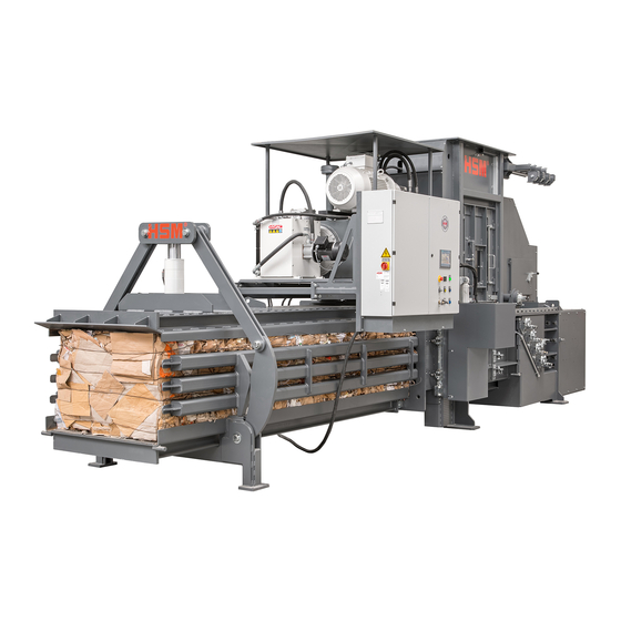
Page 18: Machine Overview
VK 5012 Technical data Machine overview Press channel Press channel adjustment Hopper Inspection door Precompactor Wire insertion cylinders Wire insertion unit maintenance door Twisting unit Twisting unit maintenance door Press ram maintenance flap Control cabinet Oil tank Wire station Wire brake 6.417.999.120... - Page 19 Technical data VK 5012 Press ram lock Oil cooler Main drive motor and pump Oil level gauge Motor and pump for press channel adjustment Valve block Venting filter Wire insertion unit Wire insertion cylinder Needle head Issued 06/2005 6.417.999.120...
- Page 20 VK 5012 Technical data Guide roller Twisting unit Twisting motor Wire shear cylinder Twisting disc Twisting rod Press cylinder Press ram with manual central lubrication Counting wheel Cutting edge clearing device 6.417.999.120 Issued 06/2005...
-
Page 21: Machine Characteristics
Technical data VK 5012 Machine characteristics Machine designation Channel baling press Machine type HSM VK 5012 Total machine weight ~ 9500 kg Strapping Quadruple Special wire ø 3.1 mm (oiled) - 40 kg wire coil Press data Pressing power 450 kN Spec. -
Page 22: Twisting Motor
VK 5012 Technical data 3.4.8 Twisting motor Type OMH 315 hydraulic motor Operating pressure 90/190 bar 3.4.9 Wire shearing cylinder Dimensions ø50/30 x 65 mm stroke 3.4.10 Oil tank Oil volume ~ 300 l Oil type As DIN 51524-T3 Multi-grade oil ISO viscosity grade HVLP 46 Press channel adjustment 3.5.1... -
Page 23: Switchbox Heating
3 x 63 A (slow-blow) 3.10 Noise emission In accordance with the DIN 45635 Part 27, the sound pressure level of the HSM VK 5012 is as follows. The distance is measured between the testing device and the machine. Idle running 1 m... - Page 24 VK 5012 Technical data 6.417.999.120 Issued 06/2005...
-
Page 25: Installation
Installation VK 5012 Installation Transport Proceed with particular care during the transport of the channel baling press to prevent damage caused by the application of force or careless loading and unloading. For loading and unloading, the whole channel baling press may be lifted with a hoist (crane or fork-lift) only at the pick-up points. - Page 26 VK 5012 Installation For the transport to the installation site, the baling press must be jacked up at the legs (1) on both sides. Position heavy-duty rollers (2) on the left and the right beneath the T-beams and put one square timber (3) onto it, ranging the whole width.
-
Page 27: Installation Conditions
-> Use heavy-duty plugs. 4.2.2 Installation personnel Warning! The baling press my only be assembled or dismantled under the supervision of an HSM service engineer. 4.2.3 Operation outdoors Warning! Put into operation only under supervison. The operator must ensure that unauthorized persons do no have access to the baling press. - Page 28 VK 5012 Installation 6.417.999.120 Issued 06/2005...
-
Page 29: Start-Up
Installation VK 5012 Start-up Initial position of the baling press • Precompactor in rear position (cylinder retracted) • Press ram in rear limit position (press cylinder retracted) • Press ram lock in rear position (cylinders retracted) • Wire insertion cylinders retracted (cylinders retracted) •... - Page 30 VK 5012 Installation COROS OP 17 SIEMENS Display Zuführband Pause Zuführband Feeding Pause feeding conveyor conveyor Not-Aus Lampentest Emergency-off Betriebsbereit Lamp check Motor Ready for operation Betriebsart Einrichten Ballen fertig Umreifen Ballenlänge Operating mode Setup Bale ready Strapping Bale length...
-
Page 31: Ready
Installation VK 5012 5.2.3 Ready “Ready” The green lamp lights up when the baling press is ready for operation. Preconditions: • The main switch is on • The emergency stop button has not been pressed • All protective and inspection doors are closed •... - Page 32 VK 5012 Installation COROS OP 17 SIEMENS Display Zuführband Pause Zuführband Feeding Pause feeding conveyor conveyor Not-Aus Lampentest Betriebsbereit Emergency-off Lamp check Motor Ready for operation Betriebsart Einrichten Ballen fertig Umreifen Ballenlänge Operating mode Setup Bale ready Strapping Bale length...
-
Page 33: Automatic Mode
Installation VK 5012 5.2.7 Automatic mode “Automatic On” Press the button “Automatic mode” The yellow lamp lights up. “Automatic Off” Press the button “Automatic mode” The yellow lamp goes out. “Automatic Off” If you press the button during automatic mode, the current pressing cycle is completed, the press ram returns to its initial position and the press “Manual mode”. -
Page 34: 12Luminous Push-Buttons: Pause Feeding Conveyor
VK 5012 Installation 5.2.12 Luminous push-buttons: Pause feeding conveyor The conveyors only operate in automatic mode! „Pause feeding conveyor“ Press the button The conveyor is switched to pause and the illuminated push-button and flashing. corresponding white indicator light is „Feeding conveyor“... - Page 35 Installation VK 5012 Compacting programs – Manual mode (press ram forwards and backwards; without precompactor; low pressure) – Computer paper (without precompactor; low pressure) – Computer paper (without precompactor; high pressure) – Plastic foil (with precompactor; low pressure) – Plastic foil (with precompactor;...
- Page 36 VK 5012 Installation 5.2.14 OP 17 operating panel The OP 17 operating panel is operated using a keypad. The keypad is composed of two functional blocks: • System keys (numerical block and control keys) • Function keys All operating conditions and malfunctions are shown on the keypad display.
-
Page 37: 1Key Functions
Installation VK 5012 5.2.14.1 Key functions Function Purpose Go back to previous level. Escape Field inputs can be cancelled provided they have not been confirmed by pressing the ENTER key. Acknowledge fault messages. Acknowledge The corresponding ACK LED • Flashes if there are any unacknowledged fault messages •... - Page 38 VK 5012 Installation 5.2.16 Display The display indicates all operating conditions of the machine. See appendix: Operator panel OP 17 SIEMENS SIMATIC OP 17 HELP SHIFT SHIFT HELP ENTER Using the F1 ÷ F8 buttons you can select the following main menu screens: F1 ->...
-
Page 39: 18Troubleshooting On The Controls
External voltage! Voltage also present when master switch is turned off. ATTENTION ! Sous tension, même en position d'arrêt de l'interrupteur principal. Troubleshooting on the controls: -> Fill in the diagnostic form and fax it to HSM. Issued 06/2005 6.417.999.120 5.11... - Page 40 VK 5012 Installation 5.2.18 Troubleshooting on the controls - Fill in the diagnostic form and fax it to HSM. 6.417.999.120 Issued 06/2005 5.12...
-
Page 41: Operating Modes
Installation VK 5012 Operating modes 5.3.1 Set-up mode Caution! In this operating mode certain electrical safety functions are disabled. Only specially trained staff may operate the machine in Set-up mode. The key must always be removed. “Set-up” Turn the key-operated switch to the I position. - Page 42 VK 5012 Installation Press ram forward (in pressing direction) Press ram back (to initial position) Strapping cylinder forward (simultaneously press K9) Strapping cylinder back (simultaneously press K9) Advance wire shearing cylinder Retract wire shearing cylinder (to initial position) Close press channel see also Chapter 5.9.1...
-
Page 43: Manual Mode
Installation VK 5012 5.3.2 Manual mode “Manual mode” “Automatic mode” is only possible if is switched off. “Automatic mode” Stop - Press the button. “Automatic mode” • The yellow lamp goes out. Press ram “Forward” button Press ram “Stop” button Press ram “Back”... -
Page 44: Automatic Mode
VK 5012 Installation 5.3.3 Automatic mode Automatic mode can only be started when the baling press is in the initial position. In automatic mode you can use the nine-position “Operating mode” switch to select a pro- gram to suit the material to be pressed. -
Page 45: Reloading The Baling Press
Installation VK 5012 Reloading the baling press If the baling press needs to be reloaded, in other words if there is no material in the press channel (for example after maintenance work, etc.), the procedure is as follows: Precondition: The wooden frame is braced in the press channel -> see “Clearing the press”... - Page 46 VK 5012 Installation Caution! If you do not adjust the flow according to these instructions you may damage the press cylinder. Note When the press is delivered, the flow limiter is screwed in by 10 turns, which means that as soon as the press is loaded and the press ram is first moved under pressure, the flow limiter can be screwed out again.
- Page 47 Installation VK 5012 Carry on pressing until the wooden frame is pushed out of the press channel. Caution! The wooden frame may be ejected suddenly from the press channel. Therefore maintain a safe distance and isolate the danger zone. “Automatic Stop”...
-
Page 48: Inserting The Strapping Wires
Quadruple strapping / ø 3.1 mm strapping wire 40 kg wire coil 6.661.993.100 Caution! Always use special HSM strapping wire. The wire must be oiled and not rusty, otherwise components of the wire station may be damaged. Staff can cut themselves on sharp wire ends and should therefore always wear safety gloves. - Page 49 Installation VK 5012 Open the inspection door. Loosen the nuts on the eye bolts on both sides and swing the twisting unit to one side. Thread the beginning of the wire through both slots and the guide bush behind (1).
- Page 50 VK 5012 Installation Push the wire through the opening in the frame and let the end protrude by approximately 400 mm. Repeat the above steps for all four wires. Swing the twisting unit back towards the press and tighten the nuts of the eye bolts.
-
Page 51: Wires On The Insertion Side
Installation VK 5012 5.5.2 Wires on the insertion side Undo the wires holding the wire coils together in the wire stations and pull the beginning of the wire out of the core of the coil. Thread the wire through the wire brake. - Page 52 VK 5012 Installation Push the wire through the slot in the frame and the guide bush behind (3). Pull the wire in front of the guide roller (4) and on towards the press channel. Push the wire through the opening in the frame and pull it up to the square tube on the press channel.
- Page 53 Installation VK 5012 Swing the insertion unit back towards the press and tighten the nuts of the eye bolts. Close the inspection door. Material used Strapping wire ø 3.1 mm / 40 kg coil Part no.: 6.661.993.100 Issued 06/2005 6.417.999.120...
- Page 54 VK 5012 Installation - Turn on the main switch “Bale ready” - Perform strapping manually using the key-operated switch once a minimum bale length of approx. 400 mm is reached. “Bale ready” - Turn the switch briefly to the right •...
-
Page 55: Automatic Compression
Installation VK 5012 Automatic compression Preconditions: • The main switch is on “emergency stop” • The button has not been pressed • All protective and inspection doors are closed • The pre-compactor and press ram are in their initial positions •... -
Page 56: Strapping Procedure
VK 5012 Installation Strapping procedure The press ram moves forward and stops under pressure. The press ram lock cylinders move forward and arrest the press ram. The wire insertion cylinders push the wires through the channels of the press ram to the twisting unit. - Page 57 Installation VK 5012 The wires are immediately twisted by the twisting unit. The wire insertion cylinders return to their initial position. The press ram is unlocked and returns to its rear limit position. The twisting rods perform three backward rotations and eject the twisted wire ends.
-
Page 58: End Of Wire
VK 5012 Installation End of wire The passage of the wires through the machine is monitored by proximity switches (1) in the wire station. If no more wire runs past one of the proximity switches, the error message • END OF WIRE • appears in the display. - Page 59 - Use the old wire to pull the new wire through the guides to the beginning of the press channel. (Position B) - Cut off the wire loop and twist the ends of the wires together using pliers. ✕ ✔ HSM strapping wire ø 3.1 mm (oiled) 40 kg coil Part no.: 6.661.993.100 Issued 06/2005 6.417.999.120...
-
Page 60: Clearing The Press Channel
VK 5012 Installation Clearing the press channel Caution! Only authorised, trained staff may carry out work in Set-up mode. When the press channel needs clearing proceed as follows: Once the last bale has been strapped: “Automatic Off” - Press “Manual •... - Page 61 Installation VK 5012 Before starting up the press again: - Place a wooden frame in the press channel (roughly below the press channel adjustment facility) and lower press channel cover again - Close the press channel -> K 7 function...
-
Page 62: Relieving The Press Channel
VK 5012 Installation 5.9.1 Relieving the press channel After shearing the material is compressed and pushed into the tapered press channel. The pressure in the press cylinder is monitored by a pressure transducer on the control block. The opening and closing of the press channel adjustment unit depends on the properties of the material or the pressing power. -
Page 63: Shutdown
Installation VK 5012 5.10 Shutdown “Automatic Stop” - Press the button • The current cycle is completed and all cylinders return to their initial positions. Initial position: • Precompactor in rear position (cylinder retracted) • Press ram in rear limit position (press cylinder retracted) •... - Page 64 VK 5012 Installation 6.417.999.120 Issued 06/2005 5.36...
-
Page 65: Inspection And Maintenance Work
Inspection and maintenance work VK 5012 Inspection and maintenance work Notes on maintenance Malfunctions which are due to inadequate or incorrect maintenance can lead to expensive repairs and lengthy machine down-times. Regular maintenance is therefore essential. For this reason we recommend a maintenance and inspection contract. -
Page 66: Maintenence Overview
VK 5012 Inspection and maintenance work Maintenence overview Area Page Interval Changing the hydraulic oil 2000 h / once a year Changing the venting filter 2000 h / once a year Changing the pressure filter element 2000 h / once a year... -
Page 67: Maintenance Intervals
Inspection and maintenance work VK 5012 6.2.1 Maintenance intervals The maintenance intervals listed here apply to single-shift operation. 1 - Shift - Operation 170 h = 1 month 500 h = 3 months 1000 h = 6 months 1500 h = 9 months 2000 h = 1 year 6.2.2... -
Page 68: Maintenance
VK 5012 Inspection and maintenance work Maintenance 6.3.1 Changing the hydrauli oil Interval: 2000 operating hours or once a year Prescribed purity grade 9 according to NAS 1638 or 6 according to SAE, ASTM, AIA. Note Observe the environmental protection regulations when disposing of waste oil. -
Page 69: Changing The Pressure Filter
Inspection and maintenance work VK 5012 Oil type: HVLP 46 hydraulic oil according to 51524-T3 Hydraulic oil type -> see “Hydraulic oil selection table” - Turn on the main switch - Advance and retract the press ram several times - With the press ram in the front limit position check the oil level in the sight glass on the hydraulic fluid tank and top it up if necessary 6.2.2... - Page 70 VK 5012 Inspection and maintenance work Before the baling press is set to operation again, the axial piston pump must be bleeded. - For that unscrew the hydraulic hose from the leakage oil port (L) and top up the pump housing with hydraulic fluid.
-
Page 71: Press Ram
• If the shear blades are damaged they must be replaced. Caution! Special skills are required for adjusting the blade clearance or press ram guide. These adjustments may only be carried out by specialist HSM staff. - Close the inspection door again 6.417.999.120 Issued 06/2005... -
Page 72: Central Lubrication, Manually
In this case, the blade clearance or press ram guide play must be adjusted. Caution! Special skills are required for adjusting the blade clearance or press ram guide. Only allow adjustments to be performed by HSM `s specialist staff. - Close maintenance door again 6.417.999.120 Issued 06/2005... -
Page 73: Press Ram Locking
Inspection and maintenance work VK 5012 6.4.3 Press ram locking Interval: 170 operating hours • With the press ram in the rear limit position - Using a grease gun pump approximately 3 strokes of multi-purpose grease into the two grease nipples on both sides of the baling press 6.417.999.120... -
Page 74: Checking The Stripper Rail
VK 5012 Inspection and maintenance work 6.4.4 Checking the stripper rail Interval: 500 operating hours With the press ram in the rear limit position • - Open the inspection door on the hopper - Unscrew the steel stripper (8) - Remove the plastic stripper rail (9) and clean it thoroughly... -
Page 75: Checking The Roller Track Stripper
Inspection and maintenance work VK 5012 6.4.5 Checking the roller track stripper Interval: 500 operating hours With the press ram in the rear limit position • - Open both maintenance doors on the back of the baling press - Check whether the roller track stripper (10) on the back of the press ram moves smoothly •... -
Page 76: Twisting Unit
VK 5012 Inspection and maintenance work Twisting unit 6.5.1 Inspecting and cleaning the shearing blades Interval: 40 operating hours With the press ram in the rear limit position • - Open the service door (7) on the twisting unit - Unscrew the eye bolts on the twisting unit and swivel it through 90°... -
Page 77: Inspecting The Twisting Disks
Inspection and maintenance work VK 5012 6.5.2 Inspecting the twisting disks Interval: 170 operating hours If twisting is poor or does not take place at all, the twisting disks (16) should be inspected immediately. • With the press ram in the rear limit position - Open the service door (7) on the twisting unit - Unscrew the eye bolts on the twisting unit and swivel itthrough 90°... -
Page 78: Lubricating The Twisting Drive
VK 5012 Inspection and maintenance work 6.5.3 Lubricating the twisting drive Interval: 1000 operating hours - Unscrew the metal lid of the protective cover • The gears and drive chains are now visible - Lubricate the gear wheels and cylinder bearing with multi-purpose grease... -
Page 79: Lubricating The Wire Guide Rollers Of The Twising Unit
Inspection and maintenance work VK 5012 6.5.4 Lubricating the wire guide rollers of the twising unit Interval: 40 operating hours • With the press ram in the rear limit position - Open the service door (7) on the twisting unit - Unscrew the eye bolts on the twisting unit and swivel it through 90°... -
Page 80: Wire Insertion Unit
VK 5012 Inspection and maintenance work Wire insertion unit 6.6.1 Cleaning and lubricating the wire insertion unit Interval: 170 operating hours With the press ram in the rear limit position • - Open the service door on the wire insertion unit - Unscrew the eye bolts on the wire insertion unit and swing it through 90°... -
Page 81: Lubricating The Wire Guide Rollers Of The Wire Insertion Unit
Inspection and maintenance work VK 5012 6.6.2 Lubricating the wire guide rollers of the wire insertion unit Interval: 40 operating hours • With the press ram in the rear limit position - Open the service door on the wire insertion unit - Unscrew the eye bolts on the wire insertion unit and swivel it through 90°... -
Page 82: Precompactor
VK 5012 Inspection and maintenance work Precompactor 6.7.1 Lubricating the journal bearings Interval: 170 operating hours - Using a grease gun pump approximately 3 strokes of multi-purpose grease into the two grease nipples on both sides of the baling press 6.7.2... -
Page 83: Wire Brake
Inspection and maintenance work VK 5012 Wire brake Interval: 1000 operating hours - Check the wire guide rollers (22) for smooth operation and change them if they are damaged - Check the drill bushes (23) for wear and change them if necessary pos. -
Page 84: Electric Motors
Warning! Maintenance and service work may be performed only by: – HSM customer service – specially trained staff (e.g. qualified electrians) – service technians from our contracting partners Before opening switch cabinet:... -
Page 85: Oil/Air Cooling Unit
Inspection and maintenance work VK 5012 6.10 Oil/air cooling unit Interval: 170 operating hours - Keep air intake grid of the cooling unit and electric motor free from blinding. Suck contamination off with a vacuum cleaner if necessary! 6.21 6.417.999.120... -
Page 86: Screw Connections
VK 5012 Inspection and maintenance work Thread sizw Tightening torque (Nm) 6.11 Screw connections Property class Property class Property class 10.9 12.9 Check the tightness of all labelled bolted joints every 170 operating hours using a torque spanner and tighten them if M 10 necessary. -
Page 87: Adjusting The Safety Rip Cord
Inspection and maintenance work VK 5012 6.12 Adjusting the safety rip cord Interval: daily The safety rip cord is activated when the blue button (C) on the rip cord switch is pushed in. The yellow button must come out when the rip cord is pulled. -
Page 88: Lubrication Chart
VK 5012 Inspection and maintenance work 6.13 Lubrication chart Item Interval Component Procedure 40 h central lubrication lubricate 170 h press ram locking lubricate 500 h roller track stripper lubricate (backside press ram) 1000 h twisting unit lubricate toothed wheels / chains... -
Page 89: Controls
- Green “RUN” LED (4) lights up BATF - Red “BATF” LED (5) does not light up DCSV FRCE STOP RUN-P STOP MRES Troubleshooting on the controls: -> Fill in the following diagnostic form and fax it to HSM. 6.25 6.417.999.120 Issued 06/2005... - Page 90 VK 5012 Inspection and maintenance work 6.417.999.120 Issued 06/2005 6.26...
-
Page 91: Using And Ordering Spare Parts
Using and ordering spare parts Note See appendix. HSM Umwelttechnik Ersatzteilliste VK 5012 - 6419P01054 (only available in German language) When ordering spare parts always quote • The complete machine number • The year of construction of the baling press... - Page 92 VK 5012 Spare parts and accessories 6.417.999.120 Issued 06/2005...
-
Page 93: Wiring And Hydraulic Diagrams
Hydraulic and wiring diagrams VK 5012 Wiring and hydraulic diagrams Note Additionally to this manual, the electrical documents for the baling press are supplied with the machine. (inside control cabinet) Issued 06/2005 6.417.999.120...
Need help?
Do you have a question about the VK 5012 and is the answer not in the manual?
Questions and answers