Table of Contents
Advertisement
Quick Links
Advertisement
Chapters
Table of Contents

Related Manuals for PCB Piezotronics Larson Davis NMS044


Summary of Contents for PCB Piezotronics Larson Davis NMS044
- Page 1 Larson Davis SoundAdvisor Model NMS044 Reference Manual...
- Page 2 Copyright Copyright 2021, by PCB Piezotronics, Inc. This manual is copyrighted, with all rights reserved. The manual may not be copied in whole or in part for any use without prior written consent of PCB Piezotronics, Inc. Trademarks in this Manual Android and the Google Play Store are trademarks of Google, LLC in the U.S.
- Page 3 Table of Contents Module 1 System Overview - - - - - - - - - - - - - - - - - - - - - - - - - - - - - - - - - - - - - - - - - - - - - - - - - 1 1.1 System Contents 1.2 Optional Accessories 1.3 Understanding NMS044 Power Consumption...
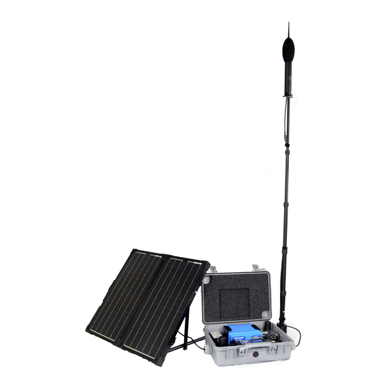
- Page 4 Module 1 System Overview The SoundAdvisor Model NMS044 noise monitoring system is the practical solution to short- or long-term, unattended sound level monitoring. Power is supplied by a 12-Volt battery, charged by a solar panel, which is positioned in an area where sunlight is most available. In this module: System Contents .........................1-2 Optional Accessories ......................1-5...
- Page 5 1.1 System Contents In this section, review your system contents to identify items received. • NMS Systems: Outdoor Equipment for Environmental Noise Monitoring • EPS Kits: Outdoor Equipment for Environmental Noise Monitoring NMS Systems: Outdoor Equipment for Environmental Noise Monitoring NMS systems are identified here in terms of the battery type and solar panel size.
- Page 6 Table 1.3 (Continued)Description of NMS044 Systems Contents Kit# Contents *Kit is available as: kit # -U: EMEA modem, PSA039 with U.S. plug kit # -E: EMEA modem, PSA039 with Int’l plug kit # -A: APAC modem, PSA039 with Int’l plug G4 LD Utility Software RV50X cellular gateway with GPS antenna (COM-RV50X)
- Page 7 EPS Kits: Outdoor Equipment for Environmental Noise Monitoring Table 1.5 lists the contents of 3 outdoor environmental kits. See Figure 1-4 for images of each item. Figure 1-4 Images of EPS044-SLA, EPS044-LFP, and EPS044 Kit Contents 3a, 3b Table 1.5 Description of EPS044-SLA, EPS044-LFP, and EPS044 Kit Contents Contents (See EPS044-SLA EPS044-LFP...
- Page 8 Table 1.6 Description and Images of Durable and Protective Case Kit (CCS051) Contents Environmentally protective case Metal case plate Power distribution block (underneath case plate) Super clamp for pole attachment Rubber Stoppers (2) one for CBL222-08 or CBL222-20, and one for EXC cable (application depends on the chosen preamplifier;...
- Page 9 The optional Scheduling firmware upgrade (831C-SCH) enables you to conserve system power and data usage while conducting measurements based on a repeatable weekly schedule with schedule blocks for the following functions: • Meter Run, Stop, Store • Specific Measurement Trigger Levels •...
- Page 10 Figure 1-7 Formula for Average Watt-hours Used Per Day = 24 (1.3 W + t (2.05 Watts)) 24hr t = time, in hours, that the modem is powered on To estimate the system run time in days, based on the available battery power, calculate the following: Figure 1-8 Formula for Days of Available Battery Power in Watt-hours Estimated...
- Page 11 Making the Most of Your Sunlight Hours For best results, we encourage you to take advantage of the most daylight and direct sun for the area of deployment. The EU Science Hub’s Solar Radiation Tool, can provide an estimate of how your system performs in a particular location based on radiation data gathered for that location in the recent past.
-
Page 12: Table Of Contents
Module 2 Getting Started Your system ships from the factory tested and assembled, except for the final battery connections and final gateway configuration details. While these can be done in the field after installation, we recommend completing these sections prior to remote installation. This module assumes that you have the complete NMS044 with all components. -
Page 13: Completing System Assembly
2.1 Completing System Assembly Figure 2-1 System Wiring Overview is shown here as reference for all system connections. Figure 2-1 System Wiring Overview PRM2103-FF Cellular Antennas Preamplifier Microphone COM-RV50X Cellular Terminal Lug Gateway (ground to plate in case) GPS Antenna Sound Level Meter... - Page 14 2.1.1 Preparing the System Battery Your NMS system ships from the factory tested and assembled, except for the final connection to the external battery. This section shows how to charge and connect the external system power. Step 1. Install the battery in the case and connect CBL225 as shown in Figure 2-2. Figure 2-2 Battery Installation Sequence Open the case and lift out the plate being careful not to pull any wires...
- Page 15 When the battery is fully charged, disconnect the AC battery charger from CBL228 as shown in Figure 2-2. • When the LED on the solar charge controller is blinking green, the battery is charging. • When the LED is solid green, the battery is nearly full or fully charged. •...
-
Page 16: Establishing Service For The Gateway
2.2 Establishing Service for the Gateway Establishing cell service for the gateway includes purchasing a SIM card with cellular service and installing it. As indicated in this section, you can also opt to have Larson Davis install and activate the SIM when your system is prepared at the factory. 2.2.1 Purchasing Cellular Service Review this section prior to purchasing cell service. - Page 17 2.2.2 Installing the SIM Card With the system powered off, install the SIM card by following these steps: Step 1. Using the provided #2 Phillips head screw driver, remove the 2 screws holding the gateway to the case plate, as shown in Figure 2-5. Step 2.
-
Page 18: Connecting The Gateway To Cellular Service
2.3 Connecting the Gateway to Cellular Service This section shows you how to use your PC to connect the gateway to your cellular service, and verify that the service is working. The final configuration details must be provided by you. This section guides you through this process. In this section: •... - Page 19 “Gateway LED Indications” on For additional information, see LEARN MORE page A-3. Step 3. Open a web browser on the connected PC, and enter “http:// 192.168.14.31:9191” into the address bar. This opens ACEmanager, the gateway configuration console. Step 4. If this is your first time logging in, log in as “user” with the password “LD_NMSystem16.”...
- Page 20 Click Change Password, then click Apply in the top right. Part 2: Entering Cellular Network Credentials Step 1. Select the WAN/Cellular menu, then choose the Cellular SIM Slot 1 Configuration sidetab as shown in Figure 2-10. Figure 2-10 WAN/Cellular tab Step 2.
- Page 21 consumption resulting from unauthorized users repeatedly attempting to connect. Setting Up the Trusted IP List Select the Security menu, then choose the Trusted IP - Inbound (Friends) sidetab. Under Inbound Trusted IP List (Inbound Trusted IP Range) enter the public IP address given to you by your cellular provider.
-
Page 22: Reviewing 831C Slm System Properties For Use With Nms044
Step 5. Leave the Password and Port fields blank unless instructed otherwise by your IT professional. Figure 2-12 Step 6. Tap the blue plus button to connect. The Meters Add Meter screen closes. If the NMS system and your mobile device have cellular service, the serial number of the 831C displays in the Meters list with a blue meter icon. -
Page 23: Using Soundlink
2.5 Using SoundLink SoundLink is an IP hosting service that provides secure communication with your remote noise monitoring systems using a dynamic IP address. This service from Larson Davis simplifies remote communication with your NMS system. It is an alternative to using a public, static IP address from your cellular provider, or a viable solution if one is not available. - Page 24 Module 3 Installing the NMS System This module demonstrates setting up the NMS044 in the field. We recommend that you review this module prior to delivering the system on site. If you want to access this information in video format, right-click LEARN MORE NMS044 Assembly and Deployment video and open the video in a new...
-
Page 25: Assembling Travel Packs
3.1 Assembling Travel Packs Assemble all components in the recommended 3 travel packs. See Figure 3-2. Figure 3-2 NMS044 Deployment Travel Packs Solar Panel in case NMS044 case with battery, Model 831C SLM, RV50X gateway, charge controller antennas, and all connections EPS2116, telescoping pole, preamplifier, and microphone, guy wire... - Page 26 Step 3. Hold the EPS2116 windscreen and birdspike together, and unscrew the top section from the bottom section. Step 4. Reassemble the top and base together. The EPS2116 should now appear in two pieces, as shown in Figure 3-4. Figure 3-4 EPS2116 Separated Birdspike Base Windscreen...
-
Page 27: Installing The Pole And Eps2116
3.3 Installing the Pole and EPS2116 Step 1. Remove the protective caps from the top and bottom of the telescoping pole. Step 2. Put the guy wire ring on the top of the pole, and position the signal cable between two mount points on the guy wire ring. Step 3. -
Page 28: Connecting The Solar Panel
Step 5. Place the pole in the clamp on the system case, and twist clamp screw clockwise to secure the pole. Figure 3-8 Telescoping Pole With Super Clamp Step 6. To extend sections of the pole, loosen the telescoping pole binders, extend the pole, and tighten the binders. -
Page 29: Powering On The Nms044 System
Step 4. Place the solar panel in a secure, unobstructed, flat location facing toward the sky with optimal sunlight. Figure 3-9 Solar Connection We recommend placing stakes or a heavy weight, like sandbags, on the solar panel legs to keep it in place. For details on disconnecting solar connectors, see Figure 2-3 on page 12. -
Page 30: Calibrating The Sound Level Meter
3.6 Calibrating the Sound Level Meter Refer to your calibrator and microphone-preamplifier product manuals for specific requirements in performing the acoustic calibration. For best results, use Larson Davis Precision Acoustic Calibrators TAKE NOTE and Larson Davis Microphone-Preamplifiers. We recommended that you calibrate the 831C after deploying the TAKE NOTE system. -
Page 31: Conducting A Final Equipment Check
Step 8. After a few seconds, a message appears indicating the measured difference and a prompt to save the results. Click Yes to save the calibration, or click No to reject it. Figure 3-12 Measured Calibration Difference Step 9. Carefully remove the calibrator from the microphone. Step 10. - Page 32 Figure 3-14 Gateway Status Indicators All gateway status indicators are “LED Indicators for RV50X shown in Cellular Gateway” on page A-3. 3.7.2 Verifying Cellular Service by Using the LD Atlas App Connecting to the 831C while in the field using the LD Atlas app helps you determine if the service is working properly.
- Page 33 3.7.4 Securing the Case With a Lock The NMS044 case latches tight, and a lock can be used to secure it. You could also chain the system to a fixed object to deter theft. Recommended next step: Module 4 Making Measurements •...
- Page 34 Module 4 Making Measurements Configuring a measurement setup file for the SoundAdvisor™ 831C sound level meter can be done prior, during, or after deployment. You can change settings, check the measurement, or download data at any time. In addition to this manual, the G4 LD Utility Manual and the SoundAdvisor 831C Manual contain a great deal of information about making measurements using Larson Davis instruments.
- Page 35 In this section: 4.1.1 Reviewing and Saving a New Setup File • • 4.1.2 Configuring the Meter to Send Alert Notifications • 4.1.3 Additional 831C Features and Settings 4.1.1 Reviewing and Saving a New Setup File If you need to customize the provided NMS044 setup file, be sure to save it with a custom name so you can reuse it another time or transfer it to a PC to be transfered to other meters.
- Page 36 For more information about using this feature, in G4 go to Help LEARN MORE Manuals G4 LD Utility 6.3 Using Scheduling Firmware. Figure 4-2 NMS044 Setup File: Time History Tab Using Time History with a 1-second Period creates one record each second in the measurement data table.
- Page 37 For more information about level and dynamic triggering, see LEARN MORE SoundAdvisor 831C Manual 17.5 Understanding Level and Dynamic Triggering. For more information on configuring alert notifications, see G4 LD Utility Manual 6.1.5 Understanding Alert Notifications Step 4. When you’re finished reviewing or editing the NMS044 Setup file, click the menu icon , and choose Setup Manager.
- Page 38 4.1.3 Additional 831C Features and Settings The SoundAdvisor 831C provides additional settings and features that may be helpful for your measurement, including the optional Scheduling firmware add-on for 831C (831C- SCH). For more information on using these features, in G4 go to Help ...
- Page 39 Appendix A Additional System Information In this module: System LED Indications .......................A-1 A.1.1 LED Indicators for SoundAdvisor™ Model 831C SLM A.1.2 LED Indicators for RV50X Cellular Gateway A.1.3 LED Indicators for Solar Charge Controllers Shipping and Storage Requirements .................A-5 A.2.1 Shipping the System A.2.2 Preparing the System for Long Term Storage...
- Page 40 System Power Indicators The system power status is indicated by the green LED behind the SLM power button Table A.1 Power Status LED Indicator Status Green LED System is powering up or FAST, SHORT GREEN BLINK shutting down Measurement Status Indicators SLM measurement status is indicated by the LEDs behind the Stop button and the Play/Pause button...
- Page 41 A.1.2 LED Indicators for RV50X Cellular Gateway When installed and running, the state of the gateway is indicated by the 4 LEDs on the side and bottom of the device. Individual lighted LEDs and combination lighted LED indications are listed in Table A.3: Table A.3 Gateway LED Indications Color/Pattern Description...
- Page 42 A.1.3 LED Indicators for Solar Charge Controllers The NMS044 solar charge controller has 1 multi-color LED which indicates unit status as shown in this section. The Genasun Lead Acid solar charge controller (Figure A-4) is one example; your model may differ slightly. Figure A-4 Example: Genasun Solar Charge Controller For LED indication details, LEARN MORE...
- Page 43 Table A.5 (Cont) Genasun Solar Charge Controller LED Indication Patterns ...LED Status Indications ...LED Error Indications Battery Charged The battery is in the Panel Voltage Too High Only 12V nominal absorption or float charging stage. solar panels may be used with this controller.
- Page 44 A.2.2 Preparing the System for Long Term Storage If you plan to store the system for more than one week, unplug and remove the battery from the case. A.2.3 Removing Cables From the Case If the cables need to be removed from the case, follow these steps. Step 1.
- Page 45 A.3 Understanding 831C SLM Connections The 831C SLM ships assembled with all required connections in place. This section shows the SLM connections from Figure 2-1 on page 10 in greater detail. There are 2 preamplifier options for the SoundAdvisor™ 831C. The PRM2103 (see Figure A- 6) is used for outdoor measurement, while the PRM831 (see Figure A-7) is most often used for indoor measurements.
- Page 46 A.4 Updating NMS044 for Modem Low Power When enabled for modem low power, the gateway is powered down except when the 831C SLM powers it on to send alert notifications. If this pattern of use is consistent with your requirements, modem low power can extend the system power supply. This feature requires the CBL222LP gateway power cable from Larson Davis, and 831C SLM firmware version 4.5 or later, as explained in the following sections.
- Page 47 A.4.3 Enabling Modem Low Power When enabled for modem low power, the gateway is powered down except for the following periods: • when the 831C SLM powers it on to send alert notifications • when the SLM sends a file to the cloud (SFTP, Dropbox, etc.) ...
- Page 48 needed. If an alert notification is sent directly following a measurement, the Alert Timeout period is in addition to the Duration. For more information about setting alert notifications through LEARN MORE your 831C account, open the G4 LD Utility Manual, Module 6.1. To do this in G4, ...
- Page 49 A.5 Configuring the Gateway for Larson Davis Instruments Complete this section ONLY if you purchased a new RV50X cellular CAUTION gateway from someone other than Larson Davis, or if it has been reset to factory default settings. Larson Davis modifies the Sierra Wireless RV50X gateway configuration to conserve power, increase security, and provide additional services.
- Page 50 Step 2. Open a web browser, and enter http://192.168.14.31:9443 in the address field. Step 3. Enter the factory default User Name and Password, and log in to ACEmanager. The factory default user name and password are labeled on the TAKE NOTE bottom of the RV50X gateway.
- Page 51 Figure A-11 Step 3. To upload the RV50X configuration template, do the following: • Download the “RV50XTemplateFile.xml” from the Larson Davis NMS044 Product Page. Then click Choose File, select the downloaded template file, and click Upload. Step 4. Select Apply. The gateway configuration is complete.
- Page 52 Step 2. Choose the WAN/Cellular menu, Ping Response sidetab; edit the values to match Figure A-12 and click Apply. Figure A-12 Edit the Ping Response Step 3. Choose the Security menu, Port Forwarding sidetab. Step 4. Edit the values to match what is shown in Figure A-13, and click Apply. Figure A-13 Edit Port Forwarding Settings Step 5.
- Page 53 Click the Power Management sidetab, and expand the Power Saving Modes menu. From the Processor Power Saving Mode drop-down, select Enable and click Apply. Figure A-15 Services - Power Management Step 7. Select the Telnet/SSH sidetab, set Telnet/SSH Echo to Disable and click Apply. This setting increases system security by blocking a potential TAKE NOTE source of unauthorized access.
- Page 54 Figure A-17 Location Settings Step 9. Choose the Local/Streaming sidetab, match the Serial and Local IP Report values shown in Figure A-18, and click Apply. Figure A-18 Local/Streaming Settings NMS044 Reference Manual Configuring the Gateway for Larson Davis Instruments A-16...
- Page 55 Step 10. Choose the Serial menu, open the Port Configuration list, select Disable from the Serial Port drop-down menu, and click Apply. Figure A-19 Serial Port Settings Step 11. Select the LAN menu, USB sidetab; verify that the settings are as shown in Figure A-20, and click Apply.
- Page 56 Step 13. Select the LAN menu, Ethernet sidetab. After this change you will not be able to connect to the gateway TAKE NOTE with a wired Ethernet connection. If you need to restore the wired connection without connecting to the gateway through the cellular connection, do a hard reset on the gateway.
- Page 57 Appendix B Technical Specifications B.1 Physical Characteristics Table B.1 Weight by Package and by Component Full Package NMS044 with 60W solar panel (SLP001), Li 23 kg (50 lbs) Battery, and cases Components NMS044 only 8.18 kg (18 lbs) 60 Watt solar panel only (SLP001) 9 kg (19.85 lbs) 100 Watt solar panel only (SLP002 ) 12.27 kg (27.05 lbs)
- Page 58 B.2 Declaration of Conformity NMS044 Reference Manual Declaration of Conformity...
- Page 59 Larson Davis - a PCB Piezotronics division LarsonDavis.com P/N INMS044.01 Rev G, NMS044 System Manual Firmware version 4.6 ©2021 PCB Piezotronics, Inc. Contact Larson Davis Toll-free (in the US): 888-258-3222 Worldwide Corporate Headquarters Phone: 716-926-8243 3425 Walden Avenue USA fax:...
Need help?
Do you have a question about the Larson Davis NMS044 and is the answer not in the manual?
Questions and answers