Table of Contents
Advertisement
Quick Links
Advertisement
Chapters
Table of Contents

Related Manuals for PCB Piezotronics Larson Davis EPS044


Summary of Contents for PCB Piezotronics Larson Davis EPS044
- Page 1 EPS044 & NMS044 Noise Monitoring System Reference Manual...
- Page 2 Larson Davis SoundAdvisor Model NMS044 Reference Manual...
- Page 3 Copyright Copyright 2019, by PCB Piezotronics, Inc. This manual is copyrighted, with all rights reserved. The manual may not be copied in whole or in part for any use without prior written consent of PCB Piezotronics, Inc. Disclaimer The following paragraph does not apply in any state or country where such statements are not agreeable with local law: Even though PCB Piezotronics, Inc.
-
Page 4: Table Of Contents
Table of Contents Module 1 System Overview 1.1 Overview ............................1-1 1.2 EPS/NMS044 Features ........................1-2 1.3 Components .............................1-2 1.4 Optional Accessories ........................1-7 1.5 Wiring Diagrams ..........................1-7 Module 2 Getting Started 2.1 Overview ............................2-1 2.2 Preparing the Battery ........................2-1 2.3 Obtaining Cellular Service for the RV50X ..................2-2 2.4 Configuring for Remote Communication ..................2-4 2.5 Configuring SLM Settings On the 831C ...................2-8 Module 3... -
Page 5: Module 1 System Overview
Module 1 System Overview Overview ..........................1-1 EPS/NMS044 Features ......................1-2 Components ........................1-2 Optional Accessories ......................1-7 Wiring Diagrams ........................1-7 1.1 Overview The SoundAdvisor Model NMS044 noise monitoring system (NMS044, system) is the practical solution to long-term or short-term, unattended sound level monitoring. -
Page 6: Eps/Nms044 Features
1.2 EPS/NMS044 Features Acoustic Measurement The area sound is measured with a prepolarized microphone and preamplifier that are environmentally protected in a shroud on a telescoping pole, which is mounted to the case. Portable The NMS044 can be deployed, before, during, or after you setup the 831C to make your measurements. - Page 7 FIGURE 1-2 CCS051 Metal plate with attached power distribution block (underneath) Rubber Stoppers EPS044 • All that is included in the CCS051 • BAT019 45 Ah 12 V LiFePo Battery or BAT020 35 Ah 12 V SLA Bat- tery • Telescoping pole with guy wire ring •...
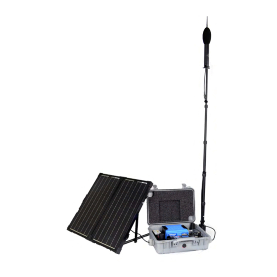
- Page 8 FIGURE 1-3 EPS044 Hardware Telescoping pole with guy wire ring PSA038 Solar Charge Controller EPS044-SLA EPS044-LFP includes the includes the 35 Ah 12 V SLA 45 Ah 12 V Battery LiFePo Battery (BAT020) (BAT019) FIGURE 1-4 EPS044 Cables CBL224-02 CBL225-01 CBL226-02 CBL228-03 NMS044 Reference Manual Rev E...
- Page 9 NMS044 • All items listed above for CCS051 and EPS044 (either the EPS044-SLA or EPS044-LFP, see Figure 1-3 EPS044 Hardware). • SoundAdvisor Model 831C Sound Level Meter (831C, SLM, meter) • Firmware options 831C-LOG, 831C-ELA and 831C-SW • Default NMS044 measurement setup •...
- Page 10 FIGURE 1-5 NMS044 Hardware PRM2103 EPS2116 preamplifier Environmental SoundAdvisor and 377B02 Protection Model 831C microphone Shroud Sound Level Meter COM-RV50X Cellular Gateway NMS044-SLP60 NMS044-SLP100 & & NMS044-LFP60 NMS044-LFP100 includes the includes the SLP001 60 W SLP002 100 W Solar Panel Solar Panel FIGURE 1-6 NMS044 Cables and Accessories...
-
Page 11: Optional Accessories
1.4 Optional Accessories • 831-MEM32G USB Flash Storage • CAL200 Precision Acoustic Calibrator • CAL250 Precision Acoustic Calibrator 1.5 Wiring Diagrams FIGURE 1-7 System Wiring Diagram PRM2103-FF Cellular Antennas Preamplifier Microphone COM-RV50X Terminal Lug Cellular Gateway (ground to plate in case) GPS Antenna Sound Level... - Page 12 The following diagram shows the wiring details for the PRM2103 outdoor preamplifier, CBL222 cable, and the 831C. FIGURE 1-8 Wiring Diagram for PRM2103 1/4” Ground Lug 18-pin CBL222 connector Case wall to I/O PRM2103 connector 5-pin connector SoundAdvisor Model 831C 10-pin connector Anderson connector to...
-
Page 13: Module 2 Getting Started
Module 2 Getting Started Overview ..........................2-1 Preparing the Battery ......................2-1 2.2.1 Installing the Battery .................... 2-1 2.2.2 Charging the Battery .....................2-2 Obtaining Cellular Service for the RV50X ................2-2 2.3.1 Installing the SIM Card ..................2-3 Configuring for Remote Communication ................2-4 2.4.1 Configuring the Gateway for Remote Comms Using USB ........ -
Page 14: Obtaining Cellular Service For The Rv50X
FIGURE 2-1 Battery Installation The yellow CAUTION connector does not connect in the power block. Do not attempt to connect the yellow connector to a red or black connector. The 831C power button controls the power in the whole system. It is used to turn off TAKE NOTE and on the NMS044. -
Page 15: Obtaining Cellular Service For The Rv50X
Step 2 The cellular plan must support a public IP address so that you can access and control the system remotely. (Often cellular providers block incoming connection requests to a SIM with a dynamic IP address.) Check with the cellular provider to assure that incoming connection requests are allowed. -
Page 16: Configuring For Remote Communication
Step 2 Using the #0 screwdriver, remove the 2 screws holding the front SIM card door. FIGURE 2-3 RV50X Sim Card Slot Step 3 Insert the SIM card into to the RV50X slot until it clicks. Step 4 Replace the SIM card door and screws. Step 5 Remount the RV50X in the case and hand-tighten the 2 case plate screws. - Page 17 Step 1 The Ethernet port on the gateway has been disabled for power saving reasons and cannot be used to connect. Disconnect the USB cable which is connected to the gateway. Step 2 Using a separate USB cable, connect the gateway directly to your computer as shown in Figure 2-4 Connecting to RV50X.
- Page 18 Step 6 Click the WAN/Cellular tab and expand the plus icon + in- line with Network Credentials. FIGURE 2-6 WAN/Cellular Step 7 Click the SIM Slot 1 Configuration sidetab, and enter the APN provided by your cellular provider in the User Entered APN field.
-
Page 19: Configuring The Gateway For Remote Comms With A Mobile Device
Step 12 Disconnect the USB cable from the PC and RV50X. Return the mini USB to the RV50X. FIGURE 2-8 Disconnecting USB/Reconnecting USB Disconnect the USB from the PC Return the mini USB to the RV50X. and RV50X Step 13 Press the ON/OFF 0 button to reboot the 831C. 2.4.2 Configuring the Gateway for Remote Comms With a Mobile Device Connecting via IP address to the 831C prior to deployment, confirms that the service is working properly. -
Page 20: Configuring Slm Settings On The 831C
Step 5 Click Apply, and reboot the gateway. 2.5 Configuring SLM Settings On the 831C Step 1 On the 831C, go to Tools System Properties, or using G4 while connected to your 831C, select your meter in the Meters Panel Live View Menu System Properties. Step 2 We recommend selecting the following basic settings when using the NMS044 system: •... -
Page 21: Module 3 Deployment
Module 3 Deployment Overview ..........................3-1 Travel Packs .........................3-2 Assemble EPS2116 and Preamplifier ................. 3-2 Install Pole and EPS2116 to System ...................3-4 Connect Solar Panel ......................3-6 Turn System ON ........................3-7 Calibrate ..........................3-8 Due Diligence ........................3-9 3.8.1 Verify Battery is Charged/Charging ..............3-10 3.8.2 Check Cellular Service ..................3-10 3.8.3... -
Page 22: Travel Packs
3.2 Travel Packs Assemble all components in the recommended three travel packs. See Figure 3-2 NMS044 Deployment Travel Packs FIGURE 3-2 NMS044 Deployment Travel Packs Solar Panel in case NMS044 case with battery, Model 831C SLM, RV50X gateway, charge controller antennas, and all connections EPS2116, telescoping... - Page 23 Step 2 Hold EPS2116 windscreen and birdspike together and unscrew from top. Screw together top and base. The EPS2116 should now appear in two components, see Figure 3-4 EPS2116 Separated. FIGURE 3-4 EPS2116 Separated Birdspike Base Windscreen Step 3 Thread the CBL222-08 cable up through the base and top. Align red dots on bottom of preamplifier to top of CBL222- 08, gently push together until mounted.
-
Page 24: Install Pole And Eps2116 To System
Step 4 Holding windscreen and birdspike over the top, screw the assemblies together (this can wait until after calibration, see “Calibrate” on page 3-8. Step 4 can be done TAKE NOTE after calibration, see “Calibrate” on page 3-8. If you need to CAUTION remove the windscreen, do not pull it off the birdspike... - Page 25 Step 2 Wrap the cable around the pole (2) two times in a counter clockwise orientation. Place into the bracket and twist clockwise to tighten. FIGURE 3-7 Telescoping Pole with EPS2116 to system Step 3 Extend the sections of the pole by loosening the telescoping pole clamp and then tighten.
-
Page 26: Connect Solar Panel
3.5 Connect Solar Panel Step 1 Unlatch solar panel to open. Step 2 Loosen thumb screws to extend legs. Match angle on either side. Step 3 Connect the solar connectors together. Step 4 Place solar panel in a secure, unobstructed flat spot facing toward the sky with optimal sunlight. -
Page 27: Turn System On
3.6 Turn System ON Press the power button 0 on the 831C to turn the whole system on. The Model 831C SLM power button 0 controls the power in the whole system. It is used to turn off and on the NMS044. FIGURE 3-10 NMS044 Case Components NMS044 Reference Manual Rev E... -
Page 28: Calibrate
3.7 Calibrate For best results, Refer to your calibrator and microphone-preamplifier product manuals TAKE NOTE use Larson Davis Precision for specific requirements in performing the acoustic calibration. Acoustic Calibrators and Larson Davis Microphone- Preamplifiers. Step 1 Holding windscreen and birdspike together, unscrew the It is recommended TAKE NOTE to perform a calibration after... -
Page 29: Due Diligence
Step 7 Afte r a fe w se conds, a me ssage appe ars indicating the measured difference and a prompt to save the results. Click Yes to save the calibration or No to reject it. Step 8 Carefully remove the calibrator from the microphone. FIGURE 3-12 Calibration Results Click the Calibration History tab to view either acoustic calibration or... -
Page 30: Verify Battery Is Charged/Charging
3.8.1 Verify Battery is Charged/Charging You will know the is battery fully charged when the PSA038 Solar Charge Controller is green. A blinking LED indicates it is charging, constantly on indicates charge is full. See A.5.3 "PSA038 Genasun Solar Charge Controller" on page A-5. 3.8.2 Check Cellular Service By connecting to the 831C while in the field, you can determine if the service is working properly. -
Page 31: Module 4 Making Measurements
Module 4 Making Measurements Overview ..........................4-1 Connecting to G4 LD Utility ....................4-1 Default NMS044 Setup File ....................4-2 Setting Up Alert Notifications .....................4-5 4.4.1 Enabling Alert Notifications for Sound Events ............ 4-6 Setting System Alert Notification Details ................4-7 4.5.1 Listening to OGG Files ..................4-10 4.1 Overview Setting up the Model 831C Sound Level Meter can be done prior, during, or after deployment. -
Page 32: Default Nms044 Setup File
4.3 Default NMS044 Setup File For convenience, there is a default setup file for the NMS044 on the meter that can be set to Active. If you make any changes to this setup, you can save it as a custom setup file for multiple use, even transferring it to a PC to be transfered to any number of meters. - Page 33 FIGURE 4-3 NMS044 Settings: Control Measurement It is recommended to set Continuous as the Run Mode for the NMS044. TAKE NOTE history is only available with This mode will begin a run every time the meter is powered on and will the 831C-ELA or 831C-MRS continue to run until a manual Stop or the meter is powered off.
- Page 34 FIGURE 4-5 NMS044 Settings: Triggers, Events, and Sound Options 831C-SR, Make event-based sound recordings that can be sent via email or SMS TAKE NOTE 831C-MSR, 831C-ELA enable and stored in the measurement data with these settings. When the area this feature and must be sound exceeds the SPL 2 or Peak 3 triggers, a sound recording will purchased and installed on begin and record 7 seconds of sound, which will immediately be sent as...
-
Page 35: Setting Up Alert Notifications
4.4 Setting Up Alert Notifications The 831C can be set up to send email and text alerts for a variety of system events, as well as measurement and sound events by using the System Properties email preferences. When an event (setting change, e xce e dance trigge r, sound e ve nt, e tc) occurs and the me te r has an active network connection, the meter sends the alert notification after the event has concluded. -
Page 36: Enabling Alert Notifications For Sound Events
Step 4. Select the Security level for the account. TLS Trusted CA (preferred) The 831C matche s re sponding se rve r with a provide d ce rtificate to verify that the responding server is known. If the responding server can’t be verified, the email will not send. -
Page 37: Setting System Alert Notification Details
send a sound recording of the exceedance (in WAV or OGG format), go to Tools Setup Manager Sound and select Save Event Sound. For the full process, see section 18.3 of the 831C SLM Reference Manual. Step 3 Run a measurement and trigger an event. The alert notification sends after the event and any continuation TAKE NOTE period passes. - Page 38 Settings When you change any setting or preference on the meter, the 831C sends an alert notification. Memory The 831C sends an alert notification when the primary memory storage (free space) is 25%, 10%, and 0%. Primary memory storage can be internal or USB.
- Page 39 FIGURE 4-8 Alert Notification Email Example Spam and Duplicate Alerts To protect recipients from receiving duplicate alert notifications for the same trigger when the state of the meter fluctuates around that trigger, the 831C has a hysteresis, or threshold, for multiple notifications that concern these specific alert details: •...
-
Page 40: Listening To Ogg Files
4.5.1 Listening to OGG Files The 831C supports interfacing with the meter using a browser. This function is in beta testing, and the functionality is not complete. Support for browsers and audio playback is summarized below: Table 4.1 Audio Playback Platform Browser Audio File (.OGG) -
Page 41: Appendix A Additional Features
Appendix A Additional Features Physical Characteristics ......................A-1 NMS044 Power Draw ......................A-2 A.2.1 Sunlight Hours ......................A-2 A.2.2 Alternative Solar Panel ..................A-2 Long Term Storage ......................A-2 Shipping Information ......................A-2 A.4.1 Lithium Iron Phosphate Battery (LiFePo) ............A-3 LED Indicators ........................A-3 A.5.1 SoundAdvisor Model 831C Sound Level Meter ............A-3 A.5.2 COM-RV50X-APAC/US:EMEA Cellular Gateway ............A-3 A.5.3... -
Page 42: Nms044 Power Draw
A.2 NMS044 Power Draw The NMS044 system draws power from the connected battery. It cannot be powered any other way (ex. wall outlet). The following table was generated from the recommended setup for the RV50X, see “Preparing the Battery” on page 2-1. Other options are available that will change the power consumption of the system and any deviation from the recommended setup. -
Page 43: Led Indicators
battery can be shipped in the case, with the correct shipping labels on the outside of the box. A.4.1 Lithium Iron Phosphate Battery (LiFePo) The BAT019 LiFePo is considered Class 9 Hazardous Material, and additional requirements will need to be met when shipping. A company and/or individual will need to be 49 CFR and IATA certified to be able to ship the BAT019 (which is a lithium battery over 100 W Hr). - Page 44 Table A.3 RV50X LED Indicators Color/Pattern Description LED Power Saving Mode Power No power or input voltage > 36 Vdc or < 7 Vdc Solid Green Power is present Green with Amber Power is present and the gateway has a GPS fix Flash Solid Red Standby mode...
-
Page 45: Psa038 Genasun Solar Charge Controller
FIGURE A-1 Gateway LED Indications A.5.3 PSA038 Genasun Solar Charge Controller The solar charger has one bicolor status LED. When you first connect your charger to the battery, the LED should blink red then green. The LED blinks green to indicate that your charger is powered and charging, and the LED may blink red to indicate errors. - Page 46 • Six Blinks Panel Too High • Two Long Blinks followed by short blinks Contact Technical Support FIGURE A-2 Genasun Solar Charge Controller LED NMS044 Reference Manual Rev E LED Indicators...
-
Page 47: Removing Cables From The Case
A.6 Removing Cables From the Case In the event that the cables need to be removed from the case, follow these steps. Step 1 Remove the CBL228-03 from the charge controller by unscrewing the terminals and gently pulling the cable out. Remove the CBL222-08 from the top of the 831C by pressing the release button and pulling out. -
Page 48: Configuring Ld Settings For The Rv50X
A.7 Configuring LD Settings for the RV50X The RV50X Gateway can only be a functioning communication device if it is configured with the correct settings. If you purchased a new RV50X from some one othe r than Larson Davis—or if it has be e n re se t to factory defaults—complete the following sections to configure your system for use with Larson Davis instruments. -
Page 49: Configuring Ld Settings Using The Template File
Changing Your Password a. Navigate to the Admin tab, and enter the default password (“12345”) in Old Password. FIGURE A-4 Admin Tab b. Enter a unique password in New Password, and again in Retype Password. c. Record your password. If you forget it you will need to reset the RV50X to factory settings and reconfigure. -
Page 50: Configuring Ld Settings Without The Template File
Step 2 Click Choose File, select the template file “RV50XTemplateFile.xml” from the LD USB drive included with your system, then click Upload. If needed, you can also access the file from http://www.LarsonDavis.com Step 3 Select Apply. The gateway configuration is complete. A.7.3 Configuring LD Settings Without the Template File If you would pre fe r to manually configure the RV50X inste ad of uploading the Template file, complete this section. - Page 51 Step 5 In the left pane, click the Power Management section, and select Power Saving Mode. Step 6 From the Processor Power Saving Mode drop-down, select Enable and click Apply. FIGURE A-7 Services - Power Management Step 7 In the left pane, select Telnet/SSH Echo, set the value to Disable and click Apply.
- Page 52 Step 8 Select the Location tab, then in the left pane, select Global Settings. Step 9 From the Location Service drop-down, choose Enable. Step 10 Set the TCP Location Port to 9494, and click Apply. FIGURE A-9 Location Settings NMS044 Reference Manual Rev E Configuring LD Settings for the RV50X A-12...
- Page 53 Step 11 In the left pane, select Local/Streaming, modify the values to match Figure A-10, and click Apply. FIGURE A-10 Local/Streaming Configuration Values Step 12 Navigate to the Events Reporting tab. Step 13 Change the Action Name to be Intrusion Detection, and the Action Type to be Email.
- Page 54 Step 15 Navigate to the Serial tab, select Disable from the Serial Port drop- down menu, and click Apply. FIGURE A-12 Serial Port Settings Step 16 Navigate to the LAN tab, and in the left pane, select the USB section. Step 17 Verify that the settings are as shown in Figure A-13, and click Apply.
- Page 55 Step 18 Navigate to the I/O tab, and select the Configuration section in the left pane. Step 19 Verify that the settings are as shown in Figure A-14, and click Apply. FIGURE A-14 After this change you will not be able to connect to the gateway with a TAKE NOTE wired Ethernet connection.
-
Page 56: Declaration Of Conformity
A.8 Declaration of Conformity NMS044 Reference Manual Rev E Declaration of Conformity A-16... - Page 57 Larson Davis - a PCB Piezotronics division LarsonDavis.com P/N INMS044.01 Rev E, Firmware version 4.0.5 ©2019 PCB Piezotronics, Inc. Worldwide Corporate Headquarters Toll-free (in the US): 888-258-3222 3425 Walden Avenue Phone: 716-926-8243 Depew, NY 14043-2495 USA USA fax: 716-926-8215 E-mail: sales@larsondavis.com...
Need help?
Do you have a question about the Larson Davis EPS044 and is the answer not in the manual?
Questions and answers