Table of Contents
Advertisement
Quick Links
Model 400-001 and 400-002NS
Confidentiality Notice
This manual is provided solely as an operational, installation, and maintenance guide and contains
sensitive business and technical information that is confidential and proprietary to GAI-Tronics.
GAI-Tronics retains all intellectual property and other rights in or to the information contained herein,
and such information may only be used in connection with the operation of your GAI-Tronics product or
system. This manual may not be disclosed in any form, in whole or in part, directly or indirectly, to any
third party.
General Information
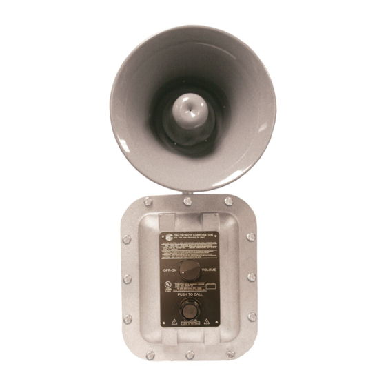
The GAI-Tronics Model 400-001 and 400-002NS RigCom Stations are designed for a common-talk, or
master/slave communication system for the following hazardous locations: Model 400-001: Class I, Div.
I, Groups C and D; Model 400-002NS: Class I, Div. I, Groups B, C, and D, when installed in accordance
with GAI-Tronics Pub. 42004-381, Control Drawing #73214. The system provides push-to-talk, release-
to-listen operation, and has a local on/off volume control switch to activate and control the volume level
for each station independently.
The Model 400-001 includes an attached speaker and
driver unit. The Model 400-002NS does not include
the speaker and driver unit, but does have a 1/2-inch
NPT hole to remotely mount and connect the speaker
driver unit to the station.
The RigCom stations have connections for an
auxiliary microphone and footswitch connection for
remote operation from the station itself.
In this operation, the auxiliary microphone replaces
the speaker as the microphone and the auxiliary
footswitch provides the same functionality as the
push-to-talk switch. With the use of auxiliary items,
the approved hazardous locations are reduced to Class
I, Div. I, Group D.
GAI-Tronics Corporation P.O. Box 1060, Reading, PA 19607-1060 USA
610-777-1374
V
ISIT WWW
G A I - T R O N I C S ® C O R P O R A T I O N
A H U B B E L L C O M P A N Y
RigCom Stations
800-492-1212
.
-
.
GAI
TRONICS
COM FOR PRODUCT LITERATURE AND MANUALS
Figure 1. Model 400-001 RigCom Station
Fax: 610-796-5954
Pub. 42004-376A
Advertisement
Table of Contents

Related Manuals for GAI-Tronics 400-001


Summary of Contents for GAI-Tronics 400-001
- Page 1 GAI-Tronics retains all intellectual property and other rights in or to the information contained herein, and such information may only be used in connection with the operation of your GAI-Tronics product or system. This manual may not be disclosed in any form, in whole or in part, directly or indirectly, to any third party.
-
Page 2: Important Safety Instructions
Model 400-001 and 400-002NS RigCom Stations Page: 2 of 22 The Model 400-001 and 400-002NS RigCom Stations are designed to be field replacements for the previous MS39xx Series RigCom stations. As a field replacement for the MS39xx Series, the Model 400 Series must be configured as an unbalanced station. -
Page 3: Installation
These enclosures must be installed by trained, qualified and competent personnel. Installation must comply with state and national regulations, as well as safety practices for this type of equipment. Model 400-001 and 400-002NS must be installed in accordance with GAI-Tronics Pub. 42004-381, Control Drawing # 73214. - Page 4 The enclosure must be securely fastened with 7/16 -inch diameter steel mounting bolts located on all four mounting feet. Stainless steel hardware is recommended for applications in corrosive environments. Refer to Figure 2 for mounting dimensions. Figure 2. Model 400-001/400-002NS Mounting Details and Conduit Entries d:\standard ioms - current release\42004 instr. manuals\42004-376a.doc 06/06...
-
Page 5: Hardware Configuration
CAUTION RISK OF ELECTRIC SHOCK, DO NOT OPEN! Figure 3. Model 400-001 RigCom Station Outline Internal The enclosure contains a single PCBA where all customer connections are made. All connections are made to the front cover by a single wiring harness with a plug. - Page 6 Pub. 42004-376A Model 400-001 and 400-002NS RigCom Stations Page: 6 of 22 Wiring Station Wiring Attach the conduit or cable glands to the ¾ inch NPT holes on the bottom of the enclosure. Feed the low- voltage wiring conduit on the left side hole, from front view, and the power wiring through the right side hole, from front view.
- Page 7 Pub. 42004-376A Model 400-001 and 400-002NS RigCom Stations Page: 7 of 22 System Line Balance Each system requires termination of the audio pair wires with the 1 kΩ/1-watt resistor assembly included with each unit. The line balance resistor assembly is made for easy installation into the customer- supplied junction box.
- Page 8 Pub. 42004-376A Model 400-001 and 400-002NS RigCom Stations Page: 8 of 22 Figure 6. Master/Slave System cable wiring greater than 4000 feet in length d:\standard ioms - current release\42004 instr. manuals\42004-376a.doc 06/06...
- Page 9 Pub. 42004-376A Model 400-001 and 400-002NS RigCom Stations Page: 9 of 22 System Wiring The maximum line length for the complete system, while still maintaining maximum output signal, is 15,000 feet for a system with less than ten stations. This is based on No. 18 AWG wire, the stations spaced equidistantly, and one station in the talk mode at a time.
- Page 10 Pub. 42004-376A Model 400-001 and 400-002NS RigCom Stations Page: 10 of 22 Field Installation Interface TB1 - Speaker Terminal Block The following is a list of connections for the speaker output terminal block, TB1. Name Pin No. Description 16-ohm terminal for external speaker connection.
- Page 11 If the header is installed in the UNBAL position, the assembly is configured for an unbalanced input signal. In systems where the external control signal is single-ended, such as previous GAI-Tronics Model MS39xx RigCom Stations, the system must be set up as an unbalanced system.
-
Page 12: Operation
Pub. 42004-376A Model 400-001 and 400-002NS RigCom Stations Page: 12 of 22 Operation The operator has access to an on-off/volume control switch and the push-to-talk switch. The on-off/volume control switch allows the operator to turn the unit on or off and adjust the volume level in the listen mode. - Page 13 Pub. 42004-376A Model 400-001 and 400-002NS RigCom Stations Page: 13 of 22 Master/Slave System In the Master/Slave configuration, a Master station controls the talk-listen function of the Slave units through external control wiring. When the Master’s push-to-talk is not activated, the Slave stations are in talk mode allowing the Master to monitor the Slave’s audio.
-
Page 14: Maintenance
Regular inspection and a good preventive maintenance program will increase the reliability of your GAI-Tronics station. The GAI-Tronics Field Service Department can formulate a service contract suited to your facility’s specific need for preventive maintenance. -
Page 15: Specifications
Pub. 42004-376A Model 400-001 and 400-002NS RigCom Stations Page: 15 of 22 Specifications AC Power Voltage..........................120 V ac, 50/60 Hz Power consumed (at nominal) Off (mute) .......................... 6 VA, 1.8 W Standby..........................7.2 VA, 3.6 W Maximum speaker out ...................... 30 VA, 27 W DC Power Voltage..............................12 V dc... - Page 16 Pub. 42004-376A Model 400-001 and 400-002NS RigCom Stations Page: 16 of 22 Approvals The models below are approved for the following hazardous areas when installed in accordance with Pub. 42004-381, Control Drawing # 73214. Model 400-001 RigCom Station: NRTL listed (USA)............Hazardous locations Class I, Div. I, Groups C & D;...
- Page 17 Interfacing a Model 400-001 RigCom Station to a MS39xx RigCom Station System The Model 400-001 RigCom Station is designed to operate as a field replacement or system addition to the MS39xx RigCom Stations. The MS39xx uses an unbalanced system for communication and uses the negative of the audio pair as the ground reference for the control signal.
- Page 18 Pub. 42004-376A Model 400-001 and 400-002NS RigCom Stations Page: 18 of 22 Figure 11. Master/Slave Configuration with the Model 400-001 as Slave Figure 12 Common Line Configuration d:\standard ioms - current release\42004 instr. manuals\42004-376a.doc 06/06...
- Page 19 Interfacing a Model 400-001 RigCom Station to EZ Page Stations The Model 400-001 RigCom Station is designed to operate as an addition to a system of EZ Page stations. The EZ Page Series and Model 400-001 Stations are designed to operate either in balanced or unbalanced systems.
- Page 20 Pub. 42004-376A Model 400-001 and 400-002NS RigCom Stations Page: 20 of 22 Figure 14 Master/Slave Unbalanced Configuration with the Model 400-001 as Slave Figure 15. Unbalanced Common Line Configuration d:\standard ioms - current release\42004 instr. manuals\42004-376a.doc 06/06...
- Page 21 Pub. 42004-376A Model 400-001 and 400-002NS RigCom Stations Page: 21 of 22 Figure 16 Master/Slave Balanced Configuration with Model 400-001 as Master Figure 17. Master/Slave Balanced Configuration with Model 400-001 as Slave d:\standard ioms - current release\42004 instr. manuals\42004-376a.doc 06/06...
- Page 22 Pub. 42004-376A Model 400-001 and 400-002NS RigCom Stations Page: 22 of 22 Figure 18 Balanced Common Line Configuration d:\standard ioms - current release\42004 instr. manuals\42004-376a.doc 06/06...
-
Page 23: Warranty
Buyer’s sole and exclusive remedy, and the warranty period on any repaired or replacement equipment shall be one (1) year from the date the original equipment was shipped. In no event shall GAI-Tronics warranty obligations with respect to equipment exceed 100% of the total cost of the equipment supplied hereunder.
Need help?
Do you have a question about the 400-001 and is the answer not in the manual?
Questions and answers