
Subscribe to Our Youtube Channel
Related Manuals for Firetrol FTA560F


Summary of Contents for Firetrol FTA560F
- Page 1 INSTALLATION AND OPERATION INSTRUCTIONS Jockey Pump Controllers - Models FTA560F, FTA560E, FTA566E...
-
Page 2: Table Of Contents
Table of Contents Warnings ......................................1 Introduction .....................................2 Mounting Controller ..................................2 Making System Pressure Connections ........................3 Making Electrical Connections ............................3 Methods of Starting/Stopping ............................4 Control Buttons and Items on Keypad ........................5 Programmable Settings ................................ 6 Keypad Programming Procedure ...........................7 Keypad Shortcuts .................................. -
Page 3: Warnings
NO VOLTAGE IS PRESENT BEFORE PROCEEDING AND ALWAYS FOLLOW GENERALLY ACCEPTED SAFETY PROCEDURES. CONTROLLER DISCONNECT SWITCH MUST BE IN THE “OFF” POSITION IN ORDER TO OPEN THE ENCLOSURE DOOR. FIRETROL, INC. CANNOT BE LIABLE FOR ANY MISAPPLICATION OR INCORRECT INSTALLATION OF ITS PRODUCTS. -
Page 4: Introduction
Introduction Firetrol FTA560 Jockey Pump Controllers are intended for use with fire pump systems. They are used for pressure maintenance in fire pump installations to prevent unnecessary cy- cling of the main fire pump. Firetrol Jockey Pump Controllers are listed by Underwriters’ Laboratories, Inc., in accor- dance with UL508, Standard for Industrial Controllers, and CAS, Standard for Industrial Control Equipment. -
Page 5: Making System Pressure Connections
Verify that the controller information is what is required on the project: • Firetrol catalog number • Motor voltage matches incoming line voltage and frequency - Confirm incoming voltage matches nameplate before energizing controller •... -
Page 6: Methods Of Starting/Stopping
Methods of Starting/Stopping • Automatic Start The controller will start automatically on low pressure detection by the pressure transduc- er when pressure drops below the programmed Start Pressure point. • Manual Start The motor can be started by pressing the START push button, regardless of the system pressure. -
Page 7: Control Buttons And Items On Keypad
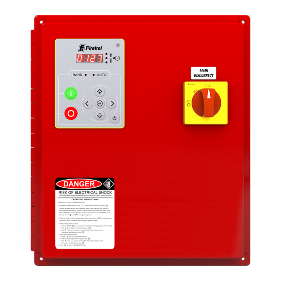
Control Buttons and Items on Keypad ON/OFF LED. It is located on the upper right-hand corner of the keypad. When this LED is lit in green, the controller is ready for automatic operation. When it is lit in red, the controller can be started in manual only (display screen will show “OFF”). -
Page 8: Programmable Settings
Programmable Settings There are five available parameters to set: 1. Pump Stop Pressure (shown on screen as “Cu.Ou” for “Cut-Out”) 2. Pump Start Pressure (shown on screen as “Cu.In” for “Cut-In”) 3. Pressure Display Units (shown on screen as “Unit”) 4. -
Page 9: Keypad Programming Procedure
Keypad Programming Procedure A. Apply power to the controller and turn ON the door mounted disconnect. If the con- troller is in OFF mode, the display screen will alternate between showing “OFF” and the incoming pressure along with a red ON/OFF LED on the upper right-hand corner of the keypad. -
Page 10: Keypad Shortcuts
Keypad Shortcuts to See Parameter Settings and Recorded Values Place controller into Auto mode by pressing ON/OFF pushbutton (for about 2 seconds) so the ON/OFF LED on the upper right-hand corner of the keypad will be lit in green. • Stop Pressure: press Up arrow button •... -
Page 11: Visual Setup Instructions
Firetrol Models: FTA560F, FTA560E, FTA566E Model # Serial # Mfg Date: Line Volt Phase / H Ctr. Volt. Max. Pres. L1 L2 L3 Ampacity NEMA Type LRC Amp Schema Options T2 T3 HAND AUTO T1 T2 T3 T1 T2 T3... - Page 12 UNIT CUT-OUT CUT-IN ON TIMER CUT-IN OFF TIMER CUT-OUT GREEN HAND AUTO HAND AUTO 2 sec.
-
Page 13: Inspections Of Controller And Operation
VISUAL INSPECTION Inspect cleanliness of controller. Remove any objects from the top of the controller. Dust and clean the controller. Inspect controller for any evidence of external corrosion. Inspect controller for any evidence of internal corrosion. Check for water leaks on pressure transducer and piping. Inspect door for proper alignment and function of door locks. - Page 14 While every precaution has been taken to ensure accuracy and completeness herein, Firetrol, Inc. assumes no responsibility, and disclaims all liability, for damages result- ing from use of this information or for any errors or omissions. Specifications and drawings are subject to change without notice. ©2021 Firetrol, Inc., All Rights Reserved.
Need help?
Do you have a question about the FTA560F and is the answer not in the manual?
Questions and answers