Table of Contents
Advertisement
Quick Links
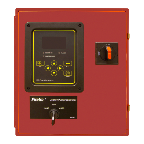
Jockey
Fire Pump Controllers
xg
3412 Apex Peakway
Apex, North Carolina 27502
P +1 919 460 5200
F +1 919 460 5250
www.firetrol.com
While every precaution has been taken to ensure accuracy and completeness herein, Firetrol, Inc. assumes no responsibility,
and disclaims all liability, for damages resulting from use of this information or for any errors or omissions. Specifications and
drawings are subject to change without notice. ©2019 Firetrol, Inc., All Rights Reserved.
Installation & Operation
NS550-01 Rev. C
ECN281257
Instructions
Advertisement
Table of Contents

Related Manuals for Firetrol Jockey XG FTA550


Summary of Contents for Firetrol Jockey XG FTA550
- Page 1 F +1 919 460 5250 www.firetrol.com While every precaution has been taken to ensure accuracy and completeness herein, Firetrol, Inc. assumes no responsibility, and disclaims all liability, for damages resulting from use of this information or for any errors or omissions. Specifications and drawings are subject to change without notice.
- Page 2 While every precaution has been taken to ensure accuracy and completeness herein, Firetrol, Inc. assumes no responsibility, and disclaims all liability, for damages result- ing from use of this information or for any errors or omissions. Specifications and drawings are subject to change without notice. ©2019 Firetrol, Inc., All Rights Reserved.
-
Page 3: Table Of Contents
Table of Contents INTRODUCTION ...........................1 MOUNTING CONTROLLER ......................1 MAKING ELECTRICAL CONNECTIONS ...................2 MAKING SYSTEM PRESSURE CONNECTIONS .................2 GENERAL START UP OPERATION ....................3 PROGRAMMING THE JOCKEY XG User Interface and Display ....................4 User Menu Structure ......................5 Programming Notes ......................6 MAIN MENU - SETTINGS System Setup Display Brightness ........................7... - Page 4 Motor & Power Phase Margin......................9 Feature Settings Low Pressure Audible ....................9 Pump Run Alarm ......................9 User Input ........................10 Cycle Interval ......................10 Operators Choice 1 ....................10 Operators Choice 2 ....................10 Reset Cycle Counts ....................10 Option Settings .......................11 MAIN MENU - EVENT LOG ......................11 MAIN MENU - DATA HISTORY ......................11 MAIN MENU - FACTORY Configuration - Model...
-
Page 5: Introduction
WITH ENERGIZED EQUIPMENT. ALWAYS VERIFY THAT NO VOLTAGE IS PRESENT BEFORE PROCEED- ING, AND ALWAYS FOLLOW GENERALLY ACCEPTED SAFETY PROCEDURES. CONTROLLER “ON-OFF” SWITCH MUST BE IN THE EXTREME “OFF” POSITION TO OPEN THE ENCLOSURE DOOR. FIRETROL BRAND PRODUCTS CANNOT BE LIABLE FOR ANY MISAPPLICATION OR INCORRECT INSTALLATION OF ITS PRODUCTS. -
Page 6: Making Electrical Connections
1. Open door of enclosure and inspect internal components and wiring for any signs of frayed or loose wires or other visible damage. 2. Verify that the controller information is what is required on the project: • Firetrol catalog number • Motor voltage and horsepower • Incoming line voltage and frequency •... -
Page 7: General Start Up Operation
Voltage Check— 1. Put the HAND-OFF-AUTO Selector Switch in the “OFF” Position. 2. Energize the incoming power feeder. WARNING RISK OF ELECTRICAL SHOCK Personal injury could occur. Service must be done with door open and power on. Personal Protective Equipment may be required. -
Page 8: User Interface And Display
Jockey User Interface and Display Directional Arrows Informational Display Used to go up and down in menu Status and System Pressure screens and change user defined User Choice 1 values User Choice 2 Switch Position Silence Alarm Button Active Alarms - Primary Status Notification Used to silence audible alarm Date-Time or Active Timer System Status LED’s... -
Page 9: User Menu Structure
Mark II User Menu Structure Main Menu Settings System Setup Date & Time Timers Feat. Settings Opt. Settings Pressure Phase Margin Low Press. Aud. Display Time On Delay Time Units (As ordered Setting Pump Run with controller) Language/Units Date Min. Run Time Start User Input Passwords... -
Page 10: Programming Notes
Programming Notes The Firetrol Jockey is multi-level password protected. User programmable functions are protected by a Level 1 password. LEVEL 1 PASSWORD 2 - 1 - 1 - 2 Indicates the level of password required to modify a setting. Note: Many menu settings feature an “enable/disable” option. These options are indicated by a “ü”... -
Page 11: System Setup Display Brightness
Jockey User Menu Settings Note: Many menu settings feature an “enable/disable” option. These options are indicated by a "ü” for enabled or a “x” for disabled. Indicates the level of password required to modify setting. System Setup - Display SYSTEM SETUP SETTINGS DISPLAY BRIGHTNESS... -
Page 12: Daylight Saving
SETTINGS DATE & TIME DAYLIGHT SAVING arrows to enable or disable automatic Daylight Saving time adjustments. Press to confirm. arrows to set number of minutes to adjust for at the beginning or end of Daylight Saving (+/-) time. Press to confirm. (DST +) “Begin”... -
Page 13: Overpressure Alarm
SETTINGS PRESSURE OVERPRESSURE ALARM arrows to enable or disable the overpressure alarm feature. Press to confirm. Limit arrows to set the pressure limit for the overpressure alarm. Press to confirm. PRESSURE SETTINGS RECORDING - DELTA arrows to set pressure delta recording limit. Press to confirm. - Page 14 USER INPUT SETTINGS FEATURE SETTINGS ENABLE arrows to enable or disable the user defined alarm. Press to confirm. ON DELAY arrows to select an on delay time before the alarm is acknowledged (0-99 seconds). Press to confirm. AUDIBLE arrows to select if the user input activates the audible alarm. Press to confirm.
- Page 15 Option Settings SETTINGS OPTION SETTINGS NOTE: The list of available options and the settings associated with them will vary with each controller. Below are the most common user defined settings that may appear. AUDIBLE arrows to enable or disable the audible alarm for selected option. Press to confirm.
- Page 16 PHASE SEQUENCE to select required phase sequence (1~, abc, cba). Press to confirm. PRESSURE SENSOR to enable or disable the use of a pressure sensor (transducer). Press to confirm. NOTE: This is a factory set parameter and under normal circumstances would never be changed. USER INPUT NUMBER to select input used for user defined option.
- Page 17 PHASE FAIL arrows to enable the phase failure test. Press to begin test. The phase failure should be indicated. arrows to disable the phase failure test. Press to end test. The phase failure should clear. PHASE REVERSE arrows to enable the phase reversal test. Press to begin test.
Need help?
Do you have a question about the Jockey XG FTA550 and is the answer not in the manual?
Questions and answers