
Related Manuals for Firetrol FTA1100 Series


Summary of Contents for Firetrol FTA1100 Series
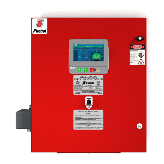
- Page 1 INSTALLATION AND MAINTENANCE GUIDE FOR MARK III DIESEL ENGINE FIRE PUMP CONTROLLERS MODEL FTA1100...
- Page 2 These instructions are intended to assist in the understanding of the installation and operation of the FTA1100. Read through these instructions thoroughly prior to connecting the controller. If there are any questions unanswered in these instructions, please contact the local Firetrol representative or factory service department. Types of Diesel Engine Fire Pump Controllers FIRE PUMP CATALOG NUMBER MODEL No.
- Page 3 OFF position. Installation Firetrol® FTA1100 combined automatic and manual diesel engine fire pump controllers are intended for starting and monitoring fire pump diesel engines. They are available for use with 12 or 24 volt negative ground systems using lead acid or Nickel-Cadmium batteries.
- Page 4 “Changes or modifications not expressly approved by the party responsible for compliance could void the user's authority to operate the equipment.” Location The controller shall be located as close as practical to the engine/motor it controls and shall be within sight of the engine/motor.
- Page 5 Check to be sure enclosure door opens freely and that enclosure is level. Storage If the controller is not installed and energized immediately, Firetrol recommend following the instructions from the chapter 3 of the NEMA ICS 15 standard. Wiring and Connections Water Connections The controller must be connected to the pipe system according to the latest edition of NFPA20 and also to a drain pipe.
- Page 6 1. Open door of enclosure and inspect internal components and wiring for any signs of frayed or loose wires or other visible damage. 2. Verify that the controller information is what is required on the project: Firetrol catalog number Engine voltage and polarity of grounding Incoming line voltage and frequency...
- Page 7 disconnecting the batteries. Disconnecting the batteries while the AC is connected may result in severe damage to the controller electronic boards. All engine connections, remote alarm functions and AC wiring must be brought into the enclosure at the bottom. (See dimension drawing for exact location).
- Page 8 Verify that the controller is installed securely to the wall, or on the mounting stand (optional). Verify the Main Selector Switch is in the “OFF” position. This selector switch is also called the “HOA” and can be placed in 3 positions: “H” Hand/Manual, “O”...
- Page 9 Open the controller's door and verify that the disconnect switch and all circuit breakers are in the “OFF” position. Verify and/or install the proper water connections for the water input and the drain. They must be securely installed and tightened. Refer to the silkscreen markings on the plastic cover. Connect all cables between the engine control panel and the controller engine terminals (Identified as “U”...
- Page 10 Activate the disconnect switch (if present) and all breakers by setting them to the "on" position. The controller will boot up for the first time.
- Page 11 Once the controller has booted up, the “First Start Up” page appears. Press the padlock icon and enter a valid authorization code. The controller will automatically detect incomming power and proper battery charger operation.
- Page 12 Turn the Main Selector Switch to the “HAND” position. Note: Before starting the engine, verify that the engine has been officially commissioned (by an authorized engine representative or service dealer) and that the exhaust pipe is connected properly. Perform an engine start on both batteries individually by pressing the associated crank button. Turn the engine off by switching the Main Selector to the “OFF”...
- Page 13 Choose the desired units of measurement for pressure reading and verify that it matches with the calibrated pressure gauge installed on the sensing line. Set the Cut-In value according to your system specifications. Cut-Out value will default to Cut- In plus 10 PSI. To manually enter the cut-out, select the check-box besides it and enter the desired value (optional). Service Done When finished, press the button.
- Page 14 Main Features The MarkIII A: Power LED 3 colors: Pulsing green if the MarkIII is properly powered. B: Crank 1 button: Used to manually crank the starter from battery 1 while in "HAND" mode. C: Crank 2 button: Used to manually crank the starter from battery 2 while in "HAND" mode. D: Stop button: Used to stop the engine if all starting conditions are gone.
- Page 15 MarkIII: Manual Rebooting Method If required, here is the procedure to manually reboot the MarkIII: 1- Turn OFF all disconnecting means to de-energize the MarkIII. The MarkIII's screen should turn black. 2- Press the stop button or wait until the MarkIII's LED extinguishes. 3- Wait 10 seconds.
- Page 16 Home Home (Menu) Home The home page displays all controller statuses and important values of the controller. This includes all voltages, currents, pressure, engine state and status. Navigation bar: Pressing this icon will open a navigation menu on the left side of the screen: 1.
- Page 17 Ammeter: Displays the actual current between the charger and the battery in amps. The battery: The battery will be red if it is in failure and green otherwise. The data shows the actual voltage of the battery and the charger in volts. Engine Speed icon: Will be green when running, read when in overspeed condition and gray otherwise.
- Page 18 The “Nameplate Information” page contains all the information found on the nameplate. The Jockey Pump Cut-Out and Cut-In can be set on this page. It is possible to install a custom Service card on this page. Contact Firetrol for more information.
- Page 19 Download Manuals Pressing on the question mark on the MarkIII will redirect to the download page. A pdf version of the manual can be downloaded on an USB device. Language The language displayed on the MarkIII can be selected on this page. Technical Documents Additonnal Technical documentation is available inside the full manual found inside the MarkIII.
- Page 20 Firetrol Inc. +1 919 460 5200 3412 Apex Peakway, Apex NC, 27502...
Need help?
Do you have a question about the FTA1100 Series and is the answer not in the manual?
Questions and answers