
Related Manuals for Firetrol Emerson Mark IIXG


Summary of Contents for Firetrol Emerson Mark IIXG
- Page 1 Installation and Operation Instructions Mark II Electric Fire Pump Controllers NS1000-50(A) ECN 237793...
-
Page 2: Table Of Contents
Table of Contents INTRODUCTION ...........................1 MOUNTING CONTROLLER ......................2 Wall Mount ...........................2 Floor/Base Plate Mount......................2-3 MAKING ELECTRICAL CONNECTIONS ..................3-4 MAKING SYSTEM PRESSURE CONNECTIONS .................4 GENERAL PRE-START UP OPERATION ....................4 GENERAL START UP OPERATION ....................4 Phase Rotation ........................5 MOTOR ROTATION FTA750, 1000, 1500, 1800, 2000, 2400 ................5 FTA1250 ..........................5 FTA1300, 1350 ...................... - Page 3 Invert ........................12 Keyboard .........................12 Language and Units Language .........................12 Pressure Units ......................12 Passwords Level 1 ........................12 Level 2 ........................12 Date & Time Time ........................12 Date .........................12 Date Format ......................12 Daylight Saving ......................13 Timers On Delay ........................13 Minimum Run / Off Delay ..................13 Acceleration ......................13 SS Bypass .........................13 Pressure...
- Page 4 Digital Soft Start (continued) Timeout Enabled ...................15 Timeout ......................15 No Current At Run ..................16 CT Ratio ......................16 TX ........................16 RX ........................16 Error ......................16 Trim Voltage ........................16 Alarm Limits Overpressure Alarm ....................16 Volt. Min........................16 Volt. Max.........................16 Freq. Min........................16 Freq. Max.........................16 Imbalance ........................16 Overload ........................16 Feature Settings...
- Page 5 Autostart NC ......................20 User Input Number ....................20 Low Suction ......................20 Screen Saver ......................20 Confi guration - Options ....................20 Confi guration - ADC Calibration ..................20 Diagnostics Raw Input: Analog ....................20 Raw Input: Discrete ....................20 Raw Input: Keys .......................20 Raw Output: Discrete ....................20 Mark IIXG Starts .......................20 Lamp Test ........................20 Audible Test ......................21...
-
Page 6: Introduction
FTA2000 - High Voltage Starting FTA2400 - Primary Reactor Reduced High Voltage Starting Firetrol fi re pump controllers are listed, approved or certifi ed by the following approving authori- ties: Underwriters’ Laboratories, Inc., Underwriters’ Laboratories of Canada, Canadian Standards Association, New York Board of Standards and Appeals and Factory Mutual (Except FTA750 Limited Service Controllers). -
Page 7: Mounting Controller
MOUNTING CONTROLLER NOTE—Consult the appropriate job plans to determine the controller mounting location. Tools and materials (all mounting) required: 1. Assortment of common hand tools of the type used to service electromechanical equipment. 2. Drill for drilling wall/fl oor anchor holes. 3. -
Page 8: Making Electrical Connections
1. Open door of enclosure and inspect internal components and wiring for any signs of frayed or loose wires or other visible damage. 2. Verify that the controller information is what is required on the project: • Firetrol catalog number • Motor voltage and horsepower • Incoming line voltage and frequency •... -
Page 9: Making System Pressure Connections
5. Verify AC line voltage, phase and frequency with the controller data plate on the enclosure door prior to connecting. 6. Check to see that all connections are both correctly wired (in accordance with the fi eld connec- tion diagram) and tight. 7. -
Page 10: Phase Rotation
Phase Rotation If the Mark IIXG is reporting a phase reversal, see instructions in “Setting/Motor & Power/Phase Sequence”. To simulate a phase reversal for testing purposes, push and hold the phase reversal push-button located on the right hand side of the Mark IIXG with the door open (see photo on right). -
Page 11: Fta1930
4. Observe direction of motor rotation. 5. If rotation is incorrect, confi rm that the isolating switch/circuit breaker is in the OFF position, open enclosure door and reverse any two of the corresponding motor leads (T1, T2, T3, T6/T12, T4/T10, T5/T11) on the load side of both contactors 1M and 2M. For example, reverse T1 and T2 on contactor 1M and T6/T12 and T4/T10 on contactor 2M;... -
Page 12: Initial Start Up Operation
INITIAL START-UP OPERATION 1. Place circuit breaker in ON position. The pump may start immediately if system pressure is low. The PUMP RUNNING and LOW PRESSURE LED’s will be lit. 2. If the Mark IIXG is confi gured for automatic shutdown (AUTOMATIC STOP enabled), the pump motor will continue to run for the period of time set in the MIN RUN (or OFF DELAY) screen and then stop automatically, providing the STOP pressure setting has been reached. -
Page 13: Fta1300, 1350
2. MOTOR ACCELERATION timer is factory set for 2 seconds and may be fi eld adjusted if necessary. (See Mark IIXG Programming for details). CAUTION: DO NOT EXCEED THIS TIMER SETTING WITHOUT CONSULTING YOUR FIRETROL REPRE- SENTATIVE. 3. a. FTA1300 - Contactors 1M and 1S connect the motor in the WYE confi guration. The motor may not reach full speed until the MOTOR ACCELERATION timer has timed out, deenergizing 1S and energizing 2M, connecting the motor in the DELTA confi... -
Page 14: User Interface And Display
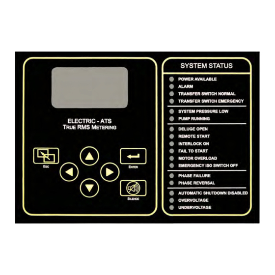
Mark II User Interface and Display SYSTEM STATUS 152 psi Running 60.3 POWER AVAILABLE Volts ALARM Amps TRANSFER SWITCH NORMAL Pump Running Min Run 7:26 TRANSFER SWITCH EMERGENCY SYSTEM PRESSURE LOW ELECTRIC - ATS PUMP RUNNING RMS M ETERING DELUGE OPEN REMOTE START INTERLOCK ON FAIL TO START... -
Page 15: User Menu Structure
Mark II User Menu Structure Main Menu Settings System Setup Date & Time Timers Motor & Power Alarm Limits Feat. Settings Opt. Settings Pressure Interlock Alarm Display Time On Delay Time Units (As ordered System Volts Overpressure Low Press. Aud. with controller) Language/Units Date... -
Page 16: Programming Notes
Programming Notes The Firetrol Mark II is multi-level password protected. User programmable functions are protected by a Level 1 password. LEVEL 1 PASSWORD 2 - 1 - 1 - 2 Indicates the level of password required to modify a setting. -
Page 17: System Setup Display Brightness
Mark II User Menu Settings Note: Many menu settings feature an “enable/disable” option. These options are indicated by a "” for enabled or a “x” for disabled. Indicates the level of password required to modify setting. System Setup - Display SYSTEM SETUP SETTINGS DISPLAY... - Page 18 SETTINGS DATE & TIME DAYLIGHT SAVING arrows to enable or disable automatic Daylight Saving time adjustments. Press to confi rm. arrows to set number of minutes to adjust for at the beginning or end of Daylight Saving (+/-) time. Press to confi...
- Page 19 Pressure UNITS SETTINGS PRESSURE arrows to set preferred pressure unit system (psi, bar, kPa). Press to confi rm. SETTINGS PRESSURE START arrows to set desired pump start pressure. Press to confi rm. SETTINGS PRESSURE STOP arrows to set desired pump stop pressure. Press to confi...
-
Page 20: Timeout Enabled
SETTINGS MOTOR & POWER PHASE SEQUENCE to select required phase sequence (1~, abc, cba). Press to confi rm. Note: This setting is used to clear a false phase reversal alarm. On 3-phase systems, once proper motor rotation is con- fi rmed, if phase reversal alarm is present, change this setting to clear the alarm. (If set to abc, change to cba or vise- versa). -
Page 21: No Current At Run
NO CURRENT AT RUN This is a read only setting that is transmitted to the digital soft starter. CT RATIO This is a read only setting that is transmitted to the digital soft starter. This is a value representing communications sent to the digital soft starter. This is a value representing communications received from the digital soft starter. -
Page 22: Feature Settings
Feature Settings FEATURE SETTINGS INTERLOCK ALARM SETTINGS arrows enable or disable the alarm for Interlock On. Press to confi rm. SETTINGS FEATURE SETTINGS LOW PRESSURE AUD arrows enable or disable the audible alarm for Low System Pressure. Press to confi rm. FEATURE SETTINGS LOW SUCTION SETTINGS... -
Page 23: Option Settings
NOW IN WEEK arrows to choose current time frame in reference to the Weekly Test schedule. Press to confi rm. (Example: If test is programmed for every 2 weeks on Sunday and today were Friday then - If testing is desired to start this week, then every other week thereafter, we would now be in week 2 of 2 - If testing is desired to start on the fol- lowing Sunday, not the coming Sunday, then we would now be in week 1 of 2). -
Page 24: Remove Drive
NOTE: The Mark IIXG also features an automatic daily save function. Every day at midnight (0:00) the events for that day are written to a fi le on the USB fl ash drive. This fi le is also a text fi le (.txt) and is named for the month, in the current year folder under Firetrol (x:\Firetrol\2009\Sept.txt). MOTORSCOPE... -
Page 25: Pressure Sensor
PRESSURE SENSOR to enable or disable the use of a pressure sensor (transducer). Press to confi rm. NOTE: This is a factory set parameter and under normal circumstances would never be changed. AUTOSTART NC to enable or disable the use of a Normally Closed contact for the autostart input. Press to confi... - Page 26 AUDIBLE TEST arrows to enable the audible test. Press to begin test. The audible alarm should sound. arrows to disable the audible test. Press to end test. The audible alarm will turn off. USB TEST arrows to enable the USB test. Press to begin test.
- Page 27 About ABOUT Information is shown for: Model Number, Serial Number, Software (Part Number, Build Number, Date), and Boot Code (Part Number, Version Information and Checksum Information).
Need help?
Do you have a question about the Emerson Mark IIXG and is the answer not in the manual?
Questions and answers